Download
1 / 59
760 likes | 1.42k Views
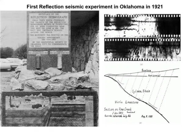
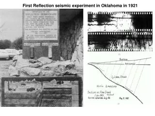
First Reflection seismic experiment in Oklahoma in 1921. Reflection Seismology. Seismic Reflection is the most important tool we have to image subsurface structure. Provides detailed imaging of approximately horizontal layering in the earth Reflection seismology is echo or depth sounding.

E N D
Reflection Seismology Seismic Reflection is the most important tool we have to image subsurface structure. Provides detailed imaging of approximately horizontal layering in the earth Reflection seismology is echo or depth sounding
Reflection Seismology A ship is moving and fires air-guns about every 10 s. The pulses travel downward and are partially reflected back up from the reflectors Waves are then recorded by seismic receivers
Seismic Section The result is a seismic section Provides a picture of the subsurface structure The resulting structure can be interpreted as stratigraphy
Seismic Section • Yet, there are reasons that the section is NOT true. • Vertical scale is not depth, but time • Actual time is two-way travel-time (down and back). • Can be converted to depth, but must know velocity structure.
Seismic Section If layering is not horizontal, reflections will not come from directly below the source. Problem solved using a migration algorithm.
Seismic Section There may be multiple reflections in addition to the primary reflections This makes artifacts. Algorithms exits to minimize.
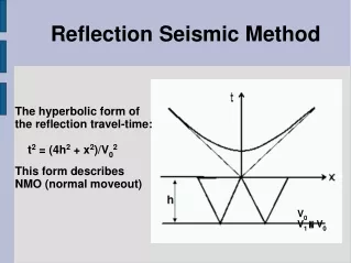
Normal Moveout (NMO) x: src—rec offset (m) T0: vertical travel-time ∆t(x): moveout wrt offset hi : ith layer thickness (m) V: layer velocity S: source coordinate R: receiver coordinate A: reflection point (mid-point of ray for flat layers). • The time to travel to a receiver a distance x away from the source is
Normal moveout derivation Normal Moveout Derivation S M R 0 x/2 x t: travel-time L: right triangle hypotenuse v: velocity of layer (km/s) t0: two-way time x: source-receiver offset h: layer thickness (km) h L L v
Normal Moveout (NMO) • Rearrange NMO equation for the velocity of the layer • to : two way travel-time (s) • x: offset from src-rec (km) • Δt(x): moveout at x-offset (s)
Multiple Layers Can solve for v2 Can iterate this procedure for deeper layers • What velocity should be used for two layers? • Answer: Root Mean Square (RMS) velocity • τi: one wave interval time (top to bottom time)
Multiple Layers: Dix formula • Another way to calculate velocity of any layer • B index: layer bottom • T index: layer top • vlayer : layer velocity • tB : 2-way tt to layer bottom • tT : 2-way tt to layer top • vrms,BRMS velocity to bottom • vrms,TRMS velocity to top
Stacking • Almost always the reflections are weak and are hard to recognize because of inevitable noise • To increase the signal-to-noise ratio, stacking is used • Take repeated measurements and average • Signal (reflections) add constructively and noise cancels
Stacking • Finding layer velocities and stacking done simultaneously • Try range of vrms • NMO correct the times of the seismograms • If the vrmsis correct strong reflections are found • If vrmsis incorrect Reflections are not found.
Dipping Reflectors • If a reflector is dipping, its apparent position and dip are wrong in an unmigrated section. • Wave raypaths are least-time paths and hence reflect from up dip points. • Unmigrated reflector is shallower and with less dip. • Travel-time hyperbola offset: h (thickness), alpha (dip)
Curved Reflectors: Syncline • If a interface is sufficiently curved, there can be more than one reflection returned from the interface: multi-pathing. • As the shot point is shifted from 1 to 10, three arrivals are produced that make a ‘bow tie’ travel-time pattern. • Migration can ‘unwrap’ the bow-tie to improve the quality of the migrated image.
Curved Reflectors: Anticline • Anticline has simpler response wrt Syncline. • An anticline seismic image is broadened • At edges of anticline two arrivals exist.
Migration • Correcting for the position and shape of the reflector is called migration • Complicated and requires large amounts of computer time • Be aware of possible distortions in un-migrated sections
Faulted Reflectors • Consider a point source (reflector). • The distance that a source-receiver measures is on the arcs shown • Multiple source-receivers produce the reflection hyperbola shown • A stepped reflector behaves normally except near the step • Produces a reflection hyperbola • Difficult to tell position of fault • Migration removes diffraction effects and reveals features more clearly
Faulted Reflectors • Migration removes diffraction effects and reveals features more clearly
Multiple Reflections • The positions of multiples can be anticipated from the position of the primary reflectors • However, sometimes it is difficult to recognize a primary reflector that comes in with the same TWT as the multiples • Can be distinguished • Moveout for the primary is less than for the multiple, so it stacks using a higher velocity
Marine Surveys • Most common source is an Air Gun • Produces P-waves (no S-waves) • Receiver is a hydrophone • Microphone that responds to change in pressure • Mounted at regular intervals and towed behind the ship in a streamer
Land Surveys • Most common source is an explosion • Buried small charge fired by detonator • Receiver is a geophone • Often times in clusters to improve s/n ratio • Moving the system on land is much harder resulting in much more expense
Data Recording • The output of each receiver is connected to an amplifier • Data is recorded digitally • sampled at regular intervals, often only 1 msec
Common Depth Point Stacking • Common Depth Point Stacking (CDP) uses rays that have all reflected from the same part of the interface • Uses pairs of shot points and receivers that are symmetrical about the reflector point • CDP stacking gives better data for computing velocities and stacking • Number of channels that are • added are the fold • 240-fold stacking is common
Static Corrections • In Land Surveys, significant topography has to be corrected for • Additionally, must take into account the effect of the topsoil and other weathered layers • Called Static Corrections • puts data on convenient • horizontal plane
Data Display • Deep reflections are weaker due to energy loss and spreading • Sometimes amplified to compensate- equalization
Vibroseis • Vibroseis produces a continuous wave with changing frequency • To find the travel time, the recorded signal is shifted in time until the entire waveform matches the source • The energy required is small • An advantage where non-intrusive is preferred
Vibroseis • The waves are generated by a vehicle with a plate that presses rhythmically against the ground • instantaneous force of 15 tonnes • 1 metric tonne =1000 kg or 2205 lb • Frequency is swept from 10 to 100 Hz over 30 sec • Sometimes several vehicles operate in unison • increases energy • has reached • Moho (30 km)
What is a Reflector? • Rays are reflected when they meet an interface • Abrupt change in seismic velocity • How abrupt? • We can define the acoustic impedance
Reflection Coefficient • Reflection coefficient • Transmission coefficient • Only valid for normal rays
Reflection Coefficient • Because the S-wave velocity and the P-wave velocities are different, their coefficients of reflection can also differ. • Sometimes S-waves are reflected more strongly than P-waves. • Consider the ratio of reflected energy Check on this
Reflection Coefficient Example • Calculate the reflection coefficient of sandstone overlying limestone. • Suppose that the properties of sandstone are at the bottom of their ranges while those of limestone are at the top
Reflection Coefficient Example • Suppose instead we have materials with different properties: • Lithological boundary, but no seismic boundary • In reality, may produce a weak reflector
Bright Spot • The interface in a hydrocarbon reservoir between a gas layer and underlying oil or water produces a strong reflection • Called a ‘bright spot’ • A strong, horizontal ‘bright spot’ • Evidence for presence of gas
Vertical Resolution • Suppose two interfaces could be brought progressively closer together • Reflected pulses would overlap more and more • At some point, the pulses cannot be resolved • The shape of the combined pulses also changes
Vertical Resolution • Often the two interfaces are two sides of a thin layer sandwiched within another • Shale layer within Sandstone • One interface has positive R and other negative • Negative R means that the reflected pulse is inverted • Interference • Can produce no reflected wave
Vertical Resolution • Since the pulse reflected from the lower interface has to travel further by twice the separation of the interfaces • Difficult to resolve when they are less than half a wavelength apart • Vertical resolution can be improved by using a shorter pulse • Shorter pulses are more rapidly attenuated • Must compromise between resolution and depth penetration
Vertical Resolution • Another situation where there is no reflection is when an interface is a gradual change of velocities and densities extending over more than about half a wavelength, rather than being abrupt • Can be thought of as many thin, sandwiched layers • Interference causes cancelation • Lithological boundary with no seismic reflector
Synthetic Reflection Seismograms • Can be used to improve interpretation • First, choose a pulse that corresponds to the source • Next, calculate the reflection and transmission coefficients • Based on borehole data • Propagate the pulse • ‘down through • the layers’
Synthetic Reflection Seismograms • If there are several interfaces closer together than the length of the average wavelength of the pulse, the reflected pulses often combine to give peaks that do no coincide with any of the interfaces
3D Surveying • We are often interested in the form of structures perpendicular to the seismic sections we have been studying • There can be reflections from dipping interfaces outside the plane of the section • Sideswipe • This can be addressed by using a regular grid on the surface (3D survey) • Often times the grid is on 50 m spacing
3D Surveying • A CDP gather comprises pairs of shot points and receivers from all around the CDP • Stacking , migration follow the same principles • Obviously more difficult and computer intensive
3D Surveying • We can think of the reflectors revealed as being embedded in a block • Can take ‘slices’ in any direction • More sophisticated processing can reveal properties of the rock such as porosity • Determines the amount • of hydrocarbon that a • rock can hold
3D Surveying • May want to add the image from plate 6 of the book here and comment on the use of porosity
Time-Lapse Modeling • By repeating surveys at intervals, the extraction of hydrocarbons can be followed and remaining pockets of oil detected • Though 3D surveying is much more expensive, both for data acquisition and reduction, it can pay for itself in the increased understanding of the structure of hydrocarbon reservoirs
Forming Hydrocarbon Reservoirs • Organic material (minute plants & animals) is buried in a source rock that protects it from oxidation (often clays in a sedimentary basin) • Bacterial action operating at temperatures of 100 to 200°C changes the organic matter into droplets of oil • The droplets are squeezed out of the source rock • Being lighter than water, usually move upward • Deformation can cause them to move sideways • Impervious cap rock (shale) prevents leakage • To be extractable, reservoir rock must be porous and permeable • To be commercially viable, must be concentrated
Hydrocarbon Traps • Structural Traps result from tectonic processes • Folds, domes, faults, etc
Hydrocarbon Traps • Stratigraphic Traps are formed by lithological variation in the strata at the time of deposition • Lens of permeable and porous sandstone or a carbonate reef, surrounded by impermeable rocks
Hydrocarbon Traps • Combination Traps have both structural and stratigraphic features • Where low density salt is squeezed upwards to form a salt dome, both tilting strata and causing hydrocarbons to concentrate as well as blocking off their escape