Download
1 / 58
630 likes | 967 Views
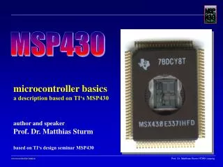
CPE 323 Introduction to Embedded Computer Systems: The MSP430 System Architecture. Instructor: Dr Aleksandar Milenkovic Lecture Notes. Outline. MSP430: System Architecture System Resets, Interrupts, and Operating Modes Basic Clock Module Watchdog Timer.

E N D
CPE 323 Introduction to Embedded Computer Systems:The MSP430 System Architecture Instructor: Dr Aleksandar MilenkovicLecture Notes
Outline MSP430: System Architecture • System Resets, Interrupts, and Operating Modes • Basic Clock Module • Watchdog Timer CPE 323
Resets • Reset – a sequence of operations that put device into a well-defined state (from which the user’s program may start) • Performed when • Power is first applied and • Device detects serious fault in hardware or software from which the user’s program cannot be expected to recover • MSP430 supports two types of reset (HW and SW controlled) • Power-on Reset (POR) • Power-up Clear (PUC) CPE 323
Power-on Reset (POR) • Generated by the following severe conditions related to hardware • Device is powered-up. POR us raised if the supply voltage drops to so low a value that the device may not work correctly. Include brownout detector. • A low external signal on the #RST/NMI pin (if the pin is configured for the reset function rather than the nonmaskable interrupt). Active by default • Some MSP430s have a more comprehensive supply voltage supervisor (SVS). It sets the SVSFG flag if the voltage falls below the programmed level and can optionally reset the device CPE 323
Power-Up Clear (PUC) • It always follows the POR. It is generated when software appears to be out of control • Watchdog time overflows in watchdog mode • Write into the watchdog control register (WDTCTL) with incorrect password in the upper byte. Can be triggered even if the WDT is disabled or operates in the interval mode • Correct password is 0x5A available as symbol WDTPW • Write an incorrect password into the flash memory controller registers (FCTLn) • Protects the stored program from a runaway software • In newer devices, a PUC is triggered when we try to fetch an instruction from the range of addresses reserved for peripheral I/O or for unimplemented memory CPE 323
Power-on Reset (POR) Powering up the device A low signal on the RST/NMI pin when configured in the reset mode An SVS low condition when PORON=1. Power-up Clear A POR signal Watchdog timer expiration when in watchdog mode only Watchdog timer security key violation A Flash memory security key violation System Reset CPE 323
Power-On Reset (POR) CPE 323
Brownout Reset CPE 323
Conditions after Reset • Initial conditions for all registers and peripherals after POR and PUC are specified in the family’s user guides; some common effects • #RST/NMI pin is configured for reset • Most I/O pins are configured as digital inputs • For registers see the manual. Notation is as follows • rw-0: means that a bit can be read and written and is initialized to 0 after a PUC • rw-(0): means that a bit can be read and written and is initialized to 0 after a POR and retains its value after a PUC • Status register is cleared (R2=0): active mode • WDT starts in watchdog mode • PC is loaded with the reset vector which is @0xFFFE CPE 323
Reset related flags • How to identify a source of the reset when debugging • IFG – Interrupt Flag Register (IFG1, IFG2) • WDTIFG: shows that the WDT timed out or its security key is violated • OFIFG: indicates an oscillator fault (causes a nonmaskable interrupt, not reset) • RSTIFG: indicates a reset caused by a signal on the #RST/NMI pin • PORIFG: is set on power-on reset • NMIIFG: flags a non-maskable interrupt caused by a signal on #RST/NMI • These bits are not cleared by a PUC, so they can be tested to identify the source of the PUC CPE 323
Software configuration Your SW must configure the MSP430 • Initialize the SP, typically to the top of RAM • Configure the watchdog to the requirements of the application • Setup the clock (clocks) • Configure all ports (unused pins should never be left as floating inputs). • Configure peripheral modules to the requirements of the application (e.g. TimerA, ADC12, ...) • Finally enable interrupts if needed • Note: Additionally, the watchdog timer, oscillator fault, and flash memory flags can be evaluated to determine the source of the reset CPE 323
Interrupts • 3 types • System reset • (Non)-maskable NMI • Maskable • Interrupt priorities are fixed and defined by the arrangement of modules CPE 323
(Non)-Maskable Interrupts (NMI) • Sources • An edge on the RST/NMI pin when configured in NMI mode • An oscillator fault occurs • An access violation to the flash memory • Are not masked by GIE (General Interrupt Enable), but are enabled by individual interrupt enable bits (NMIIE, OFIE, ACCVIE) CPE 323
NMI Interrupt Handler CPE 323
Maskable Interrupts • Caused by peripherals with interrupt capability • Each can be disabled individually by an interrupt enable bit • All can be disabled by GIE bit in the status register CPE 323
Interrupt acceptance • 1) Any currently executing instruction is completed. • 2) The PC, which points to the next instruction, is pushed onto the stack. • 3) The SR is pushed onto the stack. • 4) The interrupt with the highest priority is selected if multiple interrupts occurred during the last instruction and are pending for service. • 5) The interrupt request flag resets automatically on single-source flags. Multiple source flags remain set for servicing by software. • 6) The SR is cleared with the exception of SCG0, which is left unchanged. This terminates any low-power mode. Because the GIE bit is cleared, further interrupts are disabled. • 7) The content of the interrupt vector is loaded into the PC: the program continues with the interrupt service routine at that address. • Takes 6 cc to execute CPE 323
Return from Interrupt • RETI - Return from Interrupt Service Routine • 1) The SR with all previous settings pops from the stack. All previous settings of GIE, CPUOFF, etc. are now in effect, regardless of the settings used during the interrupt service routine. • 2) The PC pops from the stack and begins execution at the point where it was interrupted. • Takes 5 cc to execute CPE 323
Interrupt Vectors CPE 323
Interrupt Service Routine declaration // Func. declaration Interrupt[int_vector] void myISR (Void); Interrupt[int_vector] void myISR (Void) { // ISR code } Interrupt Service Routines • EXAMPLE Interrupt[TIMERA0_VECTOR] void myISR (Void); Interrupt[TIMERA0_VECTOR] void myISR (Void) { // ISR code } CPE 323
/************************************************************/************************************************************ * Interrupt Vectors (offset from 0xFFE0) ************************************************************/ #define PORT2_VECTOR 1 * 2 /* 0xFFE2 Port 2 */ #define UART1TX_VECTOR 2 * 2 /* 0xFFE4 UART 1 Transmit */ #define UART1RX_VECTOR 3 * 2 /* 0xFFE6 UART 1 Receive */ #define PORT1_VECTOR 4 * 2 /* 0xFFE8 Port 1 */ #define TIMERA1_VECTOR 5 * 2 /* 0xFFEA Timer A CC1-2, TA */ #define TIMERA0_VECTOR 6 * 2 /* 0xFFEC Timer A CC0 */ #define ADC_VECTOR 7 * 2 /* 0xFFEE ADC */ #define UART0TX_VECTOR 8 * 2 /* 0xFFF0 UART 0 Transmit */ #define UART0RX_VECTOR 9 * 2 /* 0xFFF2 UART 0 Receive */ #define WDT_VECTOR 10 * 2 /* 0xFFF4 Watchdog Timer */ #define COMPARATORA_VECTOR 11 * 2 /* 0xFFF6 Comparator A */ #define TIMERB1_VECTOR 12 * 2 /* 0xFFF8 Timer B 1-7 */ #define TIMERB0_VECTOR 13 * 2 /* 0xFFFA Timer B 0 */ #define NMI_VECTOR 14 * 2 /* 0xFFFC Non-maskable */ #define RESET_VECTOR 15 * 2 /* 0xFFFE Reset [Highest Pr.] */ Interrupt Vectors CPE 323
Clock System: An Introduction • Clock – square wave whose edges trigger hardware • Traditional clocks: a crystal with frequency of a few MHz is connected to two C pins; internally the clock may be divided by 2 or 4. • Typical application cycle in embedded systems • C stays in a low-power mode until • An event wakes up C to handle it • Often need multiple clocks (fast for CPU, slow for peripherals) • Power consumption: P ~ CV2f CPE 323
Clock System: An Introduction • Crystal clocks • Accurate (the frequency is typically within 11 part in 100,000), stable (do not change with time or temperature) • High-frequency (a few MHz) or low-frequency (32,768 Hz) for a real-time clock • Expensive, delicate, draw a relatively large current, require additional components (capacitors), take long time to start up and stabilize • Resistor and capacitor (RC) clocks • Cheap, quick to start • Poor accuracy and stability • Can be external or integrated into a chip CPE 323
MS430 Clock System • Flexible to address conflicting demands for high-performance, low-power, and a precise frequency • 3 internal clocks from 4 possible sources: MCLK, SMCLK, ACLK • Master clock, MCLK: used by the CPU and a few peripherals (e.g., ADC12, DMA, ...) • Subsystem master clock, SMCLK: distributed to peripherals • Auxiliary clock, ACLK: distributed to peripherals • Typical configuration: MCLK and SMCLK are in the megahertz range, ACLK is 32 KHz CPE 323
Clock System: MSP430 • Digitally controlled Oscillator, DCO: available in all devices; highly-controllable oscillator • Generated on-chip RC-typefrequency controlled by SW + HW • Low- or high-frequency crystal oscillator, LFXT1 • LF: 32768Hz • XT: 450kHz .... 8MHz • High-frequency crystal oscillator, XT2 • Internal very low-power, low-frequency oscillator, VLO: available in more recent MSP430F2xx devices; provides an alternative to LFXT1 when accuracy is not needed CPE 323
Basic Clock System: MSP430x1xx • DCOCLK Generated on-chip with 6s start-up • 32KHz Watch Crystal - or - High Speed Crystal / Resonator to 8MHz • (our system is 4MHz/8MHz high Speed Crystal) • Flexible clock distribution tree for CPU and peripherals • Programmable open-loop DCO Clock with internal and external current source LFXT1 oscillator 32kHz 8MHz XIN LFXT1CLK ACLK Auxiliary Clock to peripherals XOUT LFXT2CLK Clock Distribution MCLK Main System Clock to CPU 100kHz - 5MHZ Digital Controlled Oscillator DCO DCOCLK Rosc SMCLK Sub-System Clock to peripherals CPE 323
Basic Clock System – Block Diagram DIVA 2 ACLK LFXTCLK /1, /2, /4, /8 Auxiliary Clock OscOff XTS ACLKGEN SELM DIVM CPUOff High frequency 2 2 3 XT oscillator, XTS=1 MCLK 0,1 /1, /2, /4, /8, off Low power 2 Main System Clock MCLKGEN LF oscillator, XTS=0 Vcc Vcc Rsel SCG0 DCO MOD SELS DIVS SCG1 DCOCLK 3 5 2 SMCLK 0 DC- Digital Controlled Oscillator DCO 0 /1, /2, /4, /8, off + Generator Modulator MOD 1 Sub-System Clock 1 P2.5 /Rosc DCGEN DCOMOD SMCLKGEN DCOR The DCO-Generator is connected to pin P2.5/Rosc if DCOR control bit is set. The port pin P2.5/Rosc is selected if DCOR control bit is reset (initial state). CPE 323
Basic operation • After POC (Power Up Clear) MCLK and SMCLK are sourced by DCOCLK (approx. 800KHz) and ACLK is sourced by LFXT1 in LF mode • Status register control bits SCG0, SCG1, OSCOFF, and CPUOFF configure the MSP430 operating modes and enable or disable portions of the basic clock module • SCG1 - when set, turns off the SMCLK • SCG0 - when set, turns off the DCO dc generator (if DCOCLK is not used for MCLK or SMCLK) • OSCOFF - when set, turns off the LFXT1 crystal oscillator(if LFXT1CLK is not use for MCLK or SMCLK) • CPUOFF - when set, turns off the CPU • DCOCTL, BCSCTL1, and BCSCTL2 registers configure the basic clock module • The basic clock can be configured or reconfigured by software at any time during program execution CPE 323
Basic Clock Module - Control Registers The Basic Clock Module is configured using control registers DCOCTL, BCSCTL1, and BCSCTL2, and four bits from the CPU status register: SCG1, SCG0, OscOff, and CPUOFF. User software can modify these control registers from their default condition at any time. The Basic Clock Module control registers are located in the byte-wide peripheral map and should be accessed with byte (.B) instructions. Register State Short Form Register Type Address Initial State DCO control register DCOCTL Read/write 056h 060h Basic clock system control 1 BCSCTL1 Read/write 057h 084h Basic clock system control 2 BCSCTL2 Read/write 058h reset CPE 323
BCSCTL1 DCOCTL BCSCTL2 057h 056h 058h XT5V XTS DIVA.1 DIVA.0 Rsel.2 Rsel.1 Rsel.0 XT2Off DCO.2 DCO.1 DCO.0 MOD.4 MOD.3 MOD.2 MOD.1 MOD.0 SELM.1 SELM.0 DIVM.1 DIVM.0 SELS DIVS.1 DIVS.0 DCOR rw-(1) rw-(0) rw-(0) rw-(0) rw-0 rw-1 rw-0 rw-0 rw-0 rw-1 rw-1 rw-0 rw-0 rw-0 rw-0 rw-0 rw-0 rw-0 rw-0 rw-0 rw-0 rw-0 rw-0 rw-0 Basic Clock Module - Control Registers • Direct SW Control • DCOCLK can be Set - Stabilized • Stable DCOCLK over Temp/Vcc. Selection of DCO nominal frequency Define how often frequency fDCO+1 within the period of 32 DCOCLK cycles is used. Remaining clock cycles (32-MOD) the frequency fDCO is mixed Which of eight discrete DCO frequencies is selected RSEL.x Select DCO nominal frequency DCO.x and MOD.x set exact DCOCLK … select other clock tree options CPE 323
DCOCTL • Digitally-Controlled Oscillator (DCO) Clock-Frequency Control DCOCTL is loaded with a value of 060h with a valid PUC condition. 70 DCOCTL DCO.2 DCO.1 DCO.0 MOD.4 MOD.3 MOD.2 MOD.1 MOD.0 056H 0 1 1 0 0 0 0 0 MOD.0 .. MOD.4: The MOD constant defines how often the discrete frequency fDCO+1 is used within a period of 32 DCOCLK cycles. During the remaining clock cycles (32–MOD) the discrete frequency f DCO is used. When the DCO constant is set to seven, no modulation is possible since the highest feasible frequency has then been selected. DCO.0 .. DCO.2: The DCO constant defines which one of the eight discrete frequencies is selected. The frequency is defined by the current injected into the dc generator. CPE 323
BCSCTL1 • Oscillator and Clock Control Register BCSCTL1 is affected by a valid PUC or POR condition. 70 BCSCTL1 XT2Off XTS DIVA.1 DIVA.0 XT5V Rsel.2 Rsel.1 Rsel.0 057h 1 0 0 0 0 1 0 0 Bit0 to Bit2: The internal resistor is selected in eight different steps. Rsel.0 to Rsel.2 The value of the resistor defines the nominal frequency. The lowest nominal frequency is selected by setting Rsel=0. Bit3, XT5V: XT5V should always be reset. Bit4 to Bit5: The selected source for ACLK is divided by: DIVA = 0: 1 DIVA = 1: 2 DIVA = 2: 4 DIVA = 3: 8 CPE 323
BCSCTL1 Bit6, XTS: The LFXT1 oscillator operates with a low-frequency or with a high-frequency crystal: XTS = 0: The low-frequency oscillator is selected. XTS = 1: The high-frequency oscillator is selected. The oscillator selection must meet the external crystal’s operating condition. Bit7, XT2Off: The XT2 oscillator is switched on or off: XT2Off = 0: the oscillator is on XT2Off = 1: the oscillator is off if it is not used for MCLK or SMCLK. CPE 323
BCSCTL2 BCSCTL2 is affected by a valid PUC or POR condition. 70 BCSCTL2 SELM.1 SELM.0 DIVM.1 DIVM.0 SELS DIVS.1 DIVS.0 DCOR 058h Bit0, DCOR: The DCOR bit selects the resistor for injecting current into the dc generator. Based on this current, the oscillator operates if activated. DCOR = 0: Internal resistor on, the oscillator can operate. The fail-safe mode is on. DCOR = 1: Internal resistor off, the current must be injected externally if the DCO output drives any clock using the DCOCLK. Bit1, Bit2: The selected source for SMCLK is divided by: DIVS.1 .. DIVS.0 DIVS = 0:1 DIVS = 1: 2 DIVS = 2: 4 DIVS = 3: 8 CPE 323
BCSCTL2 Bit3, SELS: Selects the source for generating SMCLK: SELS = 0: Use the DCOCLK SELS = 1: Use the XT2CLK signal (in three-oscillator systems) or LFXT1CLK signal (in two-oscillator systems) Bit4, Bit5: The selected source for MCLK is divided by DIVM.0 .. DIVM.1 DIVM = 0: 1 DIVM = 1: 2 DIVM = 2: 4 DIVM = 3: 8 Bit6, Bit7: Selects the source for generating MCLK: SELM.0 .. SELM.1 SELM = 0: Use the DCOCLK SELM = 1: Use the DCOCLK SELM = 2: Use the XT2CLK (x13x and x14x devices) or Use the LFXT1CLK (x11x(1) devices) SELM = 3: Use the LFXT1CLK CPE 323
Range (RSELx) and Steps (DCOx) CPE 323
F149 default DCO clock setting CPE 323 slas272c/page 46
The DCO temperature coefficient can be reduced by using an external resistor ROSC to source the current for the DC generator. ROSC also allows the DCO to operate at higher frequencies. Internal resistor nominal value is approximately 200 kOhm => DCO to operate up to 5 MHz. External ROSC of approximately 100 kOhm => the DCO can operate up to approximately 10 MHz. External Resistor CPE 323
DCOCLK Selected f nominal Example Selected: Frequency Cycle time 1000kHz 1000 nsec f f nominal-1 nominal+1 f3: 943kHz 1060 nsec f4: 1042kHz 960 nsec MOD=19 DCOCLK Modulation Period +1 DCO f f f f f f f f +0 0 1 2 3 4 5 6 7 fDCO Basic Clock Systems-DCO TAPS • DCOCLK frequency control • nominal - injected current into DC generator 1) internal resistors Rsel2, Rsel1 and Rsel0 2) an external resistor at Rosc (P2.5/11x) • Control bits DCO0 to DCO2 set fDCO tap • Modulation bits MOD0 to MOD4 allow mixing of fDCO and fDCO+1 for precise frequency generation To produce an intermediate effective frequency between fDCO and fDCO+1 Cycle_time = ((32-MOD)*tDCO+MOD*tDCO+1)/32 = 1000.625 ns, selected frequency 1 MHz. CPE 323
reference clock e.g. ACLK or 50/60Hz SW+HW Controls the DCOCLK Vcc Vcc MOD Rsel SCG0 DCO 3 5 0 DC- Digital Controlled Oscillator DCO DCOCLK + Generator Modulator MOD 1 P2.5 /Rosc DCGEN DCOMOD DCOR Software FLL • Basic Clock DCO is an open loop - close with SW+HW • A reference frequency e.g. ACLK or 50/60Hz can be used to measure DCOCLK’s • Initialization or Periodic software set and stabilizes DCOCLK over reference clock • DCOCLK is programmable 100kHz - 5Mhz and stable over voltage and temperature CPE 323
Delta Target 1228800Hz DCOCLK source for timer 15 0 0 Capture/Compare Capture 1 Register CCR2 CCI2B Capture 2 15 0 Mode 3 Comparator 2 Stable reference ACLK/4, 8192Hz source Software FLL Implementation • Example: Set DCOCLK= 1228800, ACLK= 32768 • ACLK/4 captured on CCI2B, DCOCLK is clock source for Timer_A • Comparator2 HW captures SMCLK (1228800Hz) in one ACLK/4 (8192Hz) period • Target Delta = 1228800/8192= 150 CCI2BInt … ; Compute Delta cmp #150,Delta ; Delta= 1228800/8192 jlo IncDCO ; JMP to IncDCO DecDCO dec &DCOCTL ; Decrease DCOCLK reti IncDCO inc &DCOCTL ; Increase DCOCLK reti CPE 323
Fail Safe Operation • Basic module incorporates an oscillator-fault detection fail-safe feature. • The oscillator fault detector is an analog circuit that monitors the LFXT1CLK (in HF mode) and the XT2CLK. • An oscillator fault is detected when either clock signal is not present for approximately 50 us. • When an oscillator fault is detected, and when MCLK is sourced from either LFXT1 in HF mode or XT2, MCLK is automatically switched to the DCO for its clock source. • When OFIFG is set and OFIE is set, an NMI interrupt is requested. The NMI interrupt service routine can test the OFIFG flag to determine if an oscillator fault occurred. The OFIFG flag must be cleared by software. CPE 323
Synchronization of clock signals • When switching MCLK and SMCLK from one clock source to another => avoid race conditions • The current clock cycle continues until the next rising edge • The clock remains high until the next rising edge of the new clock • The new clock source is selected and continues with a full high period CPE 323
Basic Clock Module - Examples • How to select the Crystal Clock BCSCTL1 |= XTS; // ACLK = LFXT1 = HF XTAL BCSCTL1 |= DIVA0; // ACLK = XT1 / 8 BCSCTL1 |= DIVA1; do { IFG1 &= ~OFIFG; // Clear OSCFault flag from SW for (i = 0xFF; i > 0; i--); // Time for flag to set by HW } while ((IFG1 & OFIFG)); // OSCFault flag still set? // clock is stable BCSCTL2 |= SELM_3; // MCLK = LFXT1 (safe) CPE 323
Basic Clock Systems-Examples • Adjusting the Basic Clock The control registers of the Basic Clock are under full software control. If clock • requirements other than those of the default from PUC are necessary, the Basic • Clock can be configured or reconfigured by software at any time during program • execution. • ACLKGEN from LFXT1 crystal, resonator, or external-clock source and divided by 1, 2, 4, or 8. If no LFXTCLK clock signal is needed in the application, the OscOff bit should be set in the status register. • SCLKGEN from LFXTCLK, DCOCLK, or XT2CLK (x13x and x14x only) and divided by 1, 2, 4, or 8. The SCG1 bit in the status register enables or disables SMCLK. • MCLKGEN from LFXTCLK, DCOCLK, or XT2CLK (x13x and x14x only) and divided by 1, 2, 4, or 8. When set, the CPUOff bit in the status register enables or disables MCLK. • DCOCLK frequency is adjusted using the RSEL, DCO, and MOD bits. The DCOCLK clock source is stopped when not used, and the dc generator can be disabled by the SCG0 bit in the status register (when set). • The XT2 oscillator sources XT2CLK (x13x and x14x only) by clearing the XT2Off bit. CPE 323
FLL+ Clock Module (MSP430x4xx) • FLL+ clock module:frequency-locked loop clock module • Low system cost • Ultra-low power consumption • Can operate with no external components • Supports one or two external crystals or resonators (LFXT1 and XT2) • Internal digitally-controlled oscillator with stabilization to a multiple of the LFXT1 watch crystal frequency • Full software control over 4 output clocks: ACLK, ACLK/n, MCLK, and SMCLK CPE 323
MSP430x43x, MSP430x44x and MSP430x461x Frequency-Locked Loop CPE 323