Download
1 / 24
240 likes | 411 Views
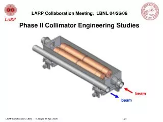
beam. beam. LARP Collaboration Meeting, LBNL 04/26/06 Phase II Collimator Engineering Studies. The Model: NLC Rotatable Collimator. s = stop roller spacing. Jaws can be rotated to present new collimation surface if damaged by beam. Typical accuracy, stability ~ 5um. beam. beam.

E N D
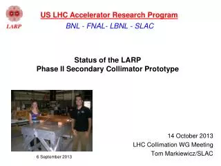
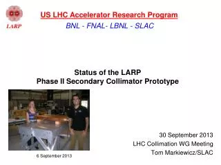
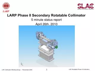
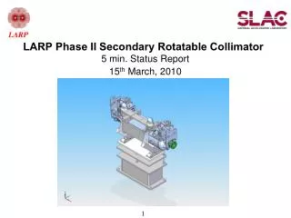
beam beam LARP Collaboration Meeting, LBNL 04/26/06Phase II Collimator Engineering Studies
The Model: NLC Rotatable Collimator s = stop roller spacing Jaws can be rotated to present new collimation surface if damaged by beam. Typical accuracy, stability ~ 5um.
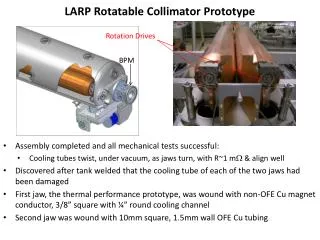
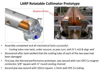
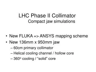
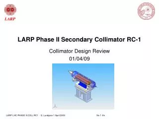
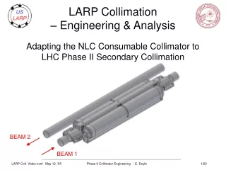
beam beam Adapted to LHC Phase II Requirements • 136mm diameter x 950 mm long jaws (750 mm effective length due to taper). • Vacuum tank, jaw support mechanism and support base derived from CERN Phase I.
Helical cooling passages chosen for manufacturablity, beamline vacuum safety Per CERN’s Phase I design – no water-vacuum weld or braze Note: baseline case has hollow core CERN PHASE I JAW POSITIONING MECHANISM – USE IF POSSIBLE EXTERNAL COIL PERMITS 1 REV OF JAW
NLC & original LHC specs – major differences * * This spec infeasible, has been relaxed Bottom Line: LHC & NLC collimators are different animals
Baseline Jaw Performance Exceeds spec, or other possible problem as noted Max Cu temp 200 Possible boiling Max water return temp Deflection 325 & 750 (SS & trans) All temperature simulations based on 20C supply. For CERN 27C supply add 7 to all temperature results. CERN max water return temp 42C
IR7 secondary collimators heat generation, deflection and effective length Deflection and effective length based on ANSYS simulations for TCSM.A6L7. Power scaled from TCSM.A6L7 according to the distribution on secondary collimators provided by CERN. Note: first collimator in the series absorbs the bulk of the energy. Steady State Transient
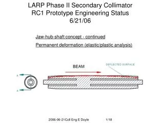
support dx=394 mm Spec: 25mm support Bending far exceeds 25um spec => Compromise: Central aperture stop prevents deflection toward beam Steady State operation 86C • Central Aperture Stop • Swelling neutralized • Bending neutralized Shaft support (Phase I) -Swelling toward beam -Bending toward beam
Adjustable central aperture-defining stop Leaf springs allow jaw end motion up to 1mm away from beam Stop in/out position controls aperture, actuator external, works through bellows.
RC1 Thermal & Mechanical Test Plan (12/05) 8 7 6 9 12 10 3 11 5 1 2 4 CY 06: Thermal RC1 Mechanical RC1 Report & RC2 planning
12/15/05 Review - Summary • Major Concerns Expressed by Review Committee • 1. Refine detailed engineering before proceeding • a. tilt stability of flexible end supports • b. accuracy of jaw fabrication & placement • c. lack of jaw indexing concept • d. cooling/thermal stability of bearings, central stop, springs, etc • 2. Possible permanent deflection due to thermal transients • 3. Try stiff core of SST to reduce deflection • 4. Insufficient manpower • SLAC’s Response • 1. Detailed engineering of mechanism proceeding (concurrent w/ thermal test) • a. reverse engineered Ph I mechanism (jaw support spring compatibility) • b. jaw will be made sufficiently accurately • c. indexing via ratchet or escapement mechanism (NLC concept) • d. began simulations of heat loads on vulnerable systems (bearings) • 2. Confirmed plastic deformation • a. adopting Glidcop as jaw material • b. begun transient analysis of errant beam “accident case” – jaw deflection • 3. SST core no benefit, solid Cu core does help, but adds weight • 4. Hired ME and designer. • a. new engineer is proceeding with thermal test (separate presentation) • Note: Schedule has slipped ~6 mo. RC1 complete 4/07
Tin M FR, Fin x Fb W Ff Jaw Positioning Forces – Phase I Ph II jaw weight on Ph I mechanism Headroom – protection against motor slippage in pull-in mode Autoretract mode – torque available to open jaws against motor detent torque in event of power failure Forces acting on screw Fb – bellows FR – spring Ff – sliding friction Fw – weight of jaw and table Torque acting on motor M – bearing friction Tout – backing out torque Torque supplied by motor Tin – pull in torque Fully retracted Operational Detent torque – when avalable torque falls below detent torque, further retraction ceases Backing out Fout = FR + Fb – Fw - Ff Tout = Fout*(back-out factor - bearing frict factor) Tout > Tdetent Pulling in Fin = FR + Fb – Fw + Ff Tin = Fin*(pull-in factor + bearing frict factor) Tin < Tmax/2
Jaw Positioning Forces – Phase I => Phase II Pull-in headroom expressed as force at nut Upper jaw - shown Lower jaw Jaw end springs will be sized as com-promise 1) bending-generated force applied to nut 2) static deflection due to jaw weight Jaw deflection = 400 um for 1 hr beam lifetime case, 1200 um for 10 sec transient @12 minute lifetime power level
NLC Jaw Indexing Mechanism Reciprocating linear motion advances jaw by one or more ratchet pitches. LHC system will require opposing ratchet to hold jaw position against cooling tube deformation torque. Mechanism probably will be designed to actuate only when jaw fully retracted.
Bimetallic jaw (SST/Cu) no benefitSolid Cu beneficial Baseline Hollow Cu SolidCu SST/Cu No benefit from SST core – same CTE as Cu, poor conductivity – temperature distribution unchanged. Cu core => alt heat path to opposite side, reduces DT therefore bending.
LHC Phase II Collimation • BONUS SLIDES
Specifications for baseline Phase II collimator * baseline design deviates * Relaxed from original spec
Unresolved Issues as of 12/15/05 • Jaw actuation mechanism • How to handle mass of rotary jaws (fail open springs) • Availability of CERN actuation mechanism for SLAC use is being discussed • Jaw rotary indexing mechanism • force to rotate jaws acceptable? • concept not developed • do we know angular position of jaw at all times? • RF parts – taper requirement details not clear • central groove in jaws (smooth track for central aperture stop) • strain-relieving grooves in jaws • what is the acceptable range of taper angles for the jaw ends • Heat generation in thin RF parts • Need details of CERN support stands, etc • Effects due to accident • does accident cause unacceptable gross distortion of the jaw? • do RF fingers work in contact with damaged surface? • How much material melts and where does it go? – depends on jaw orientation • is central aperture stop safe from contamination by melted material? • Beam tests may be required
RF contact overview Spring loaded fingers ground two jaws through range of motion Concept satisfies CERN RF requirements - Need sufficient contact pressure Cooling issues not addressed Sheet metal parts flex to follow jaw motion Clearance problems to be resolved Rigid round-square transition
Grooves reduce bending deflection Note: RF taper requirements may make this concept un-feasible • ANSYS simulation: Axial stress for un-grooved and grooved jaw with axially uniform heat input.
Cu chosen as best balance between collimation efficiency, thermal distortion & manufacturablity
Note axial gradient 89C Note more swelling than bending support dx=221 mm Spec: 25mm dx=79 mm 64% less distortion support Interesting effect: 64% less distortion if cooling is limited to a 36o arc centered on beam path. 360o full I.D. cooling 36o arc cooling Note transverse gradient causes bending 61C
beam beam water Helical and axial cooling channels illustrated 360o cooling by means of helical (or axial) channels. Pro: Lowers peak temperatures. Con: by cooling back side of jaw, increases net DT through the jaw, and therefore thermal distortion; axial flow wastes cooling capacity on back side of jaw. Limited cooling arc: free wheeling distributor – orientation controlled by gravity – directs flow to beam-side axial channels. Pro: Far side not cooled, reducing DT and thermal distortion. Con: peak temperature higher; no positive control over flow distributor (could jam); difficult fabrication.
Progression of ANSYS models – increasingly realistic Water cooled 2-d & (3-d rectangular) model 3-d “Hollow cylinder” model - Uniform or limited arc cooling “Solid” model beam Uniform ID Cooling – simulateshelical or axial channels H2O simulation – helical flow shown Tubular cooling channels