Download
1 / 67
670 likes | 698 Views
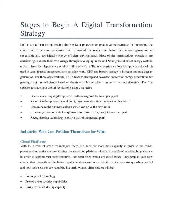
Learn how modeling, viewing, and projection transformations are crucial for vertex manipulation in OpenGL, using matrices for precise transformations. Explore the importance and application of viewing and modeling transformations.

E N D
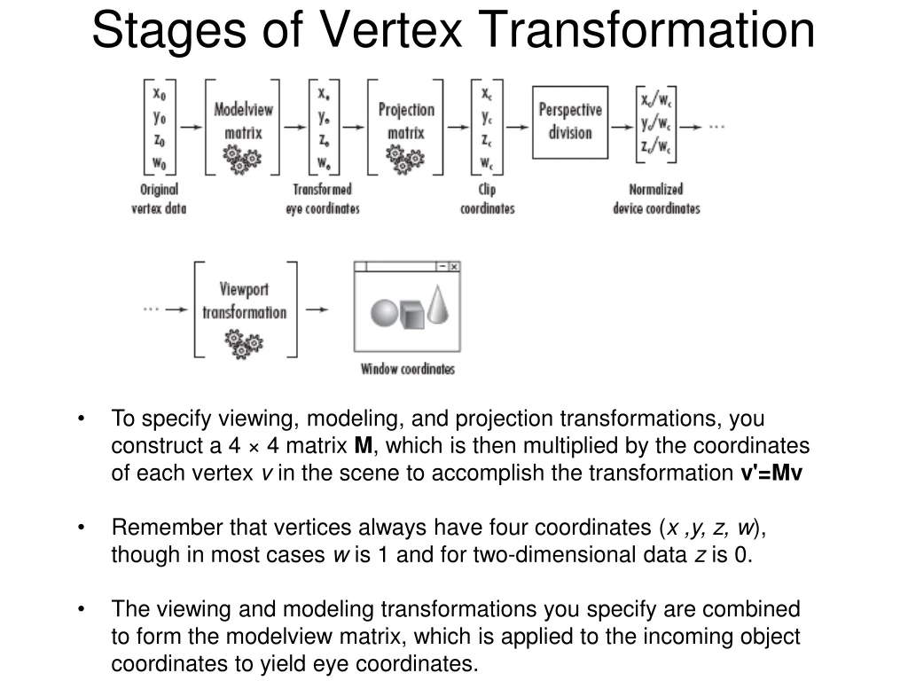
Stages of Vertex Transformation • To specify viewing, modeling, and projection transformations, you construct a 4 × 4 matrix M, which is then multiplied by the coordinates of each vertex v in the scene to accomplish the transformation v'=Mv • Remember that vertices always have four coordinates (x ,y, z, w), though in most cases w is 1 and for two-dimensional data z is 0. • The viewing and modeling transformations you specify are combined to form the modelview matrix, which is applied to the incoming object coordinates to yield eye coordinates.
Eye Coordinates (a) The eye coordinates are represented as seen by the observer of the scene (that is, perpendicular to the monitor). (b) The eye coordinate system is rotated slightly so you can better see the relation of the z-axis. • When you draw in 3D with OpenGL, you use the Cartesian coordinate system. In the absence of any transformations, the system in use is identical to the eye coordinate system.
The Viewing Transformation • The viewing transformation allows you to place the point of observation anywhere you want and look in any direction. • Determining the viewing transformation is like placing and pointing a camera at the scene. • The current matrix is set to the identity matrix with glLoadIdentity().
By default, the camera as well as any objects in the scene are originally situated at the origin; also, the camera initially points down the negative z-axis. • If the camera needed to be pointed in another direction, you could have used the glRotatef() command to change its orientation.
Modeling Transformation • Modeling transformations move objects into place, rotate them, and scale them. • Rotating and translating are performed using the commands already mentioned - glRotatef() and glTranslatef(). • Note that instead of pulling the camera back away from the cube (with a viewing transformation) so that it could be viewed, you could have moved the cube away from the camera (with a modeling transformation).
Each successive glMultMatrix*() or transformation command multiplies a new 4 × 4 matrix M by the current modelview matrix C to yield CM. • Vertices v are multiplied by the current modelview matrix: CMv. • Example glMatrixMode(GL_MODELVIEW); glLoadIdentity(); glMultMatrixf(N); /* apply transformation N */ glMultMatrixf(M); /* apply transformation M */ glMultMatrixf(L); /* apply transformation L */ glBegin(GL_POINTS); glVertex3f(v); /* draw transformed vertex v */ glEnd(); • The transformed vertex is NMLv
glMatrixMode(GL_MODELVIEW); glLoadIdentity(); glMultMatrixf(T); /* translation */ glMultMatrixf(R); /* rotation */ draw_the_object(); • The three OpenGL routines for modeling transformations are glTranslate*(), glRotate*(), and glScale*(). • All three commands are equivalent to producing an appropriate translation, rotation, or scaling matrix, and then calling glMultMatrix*() with that matrix as the argument. • void glTranslate{fd}(TYPEx, TYPE y, TYPEz); 1 0 0 x 0 1 0 y 0 0 1 z 0 0 0 1
// Translate up the y-axis 10 units glTranslatef(0.0f, 10.0f, 0.0f); // Draw the cube glutWireCube(10.0f);
void glRotate{fd}(TYPE angle, TYPE x, TYPE y, TYPE z); x^2(1−c)+c xy(1−c)−zs xz(1−c)+ys 0 yx(1−c)+zs y^2(1−c)+c yz(1−c)−xs 0 xz(1−c)−ys yz(1−c)+xs z^2(1−c)+c 0 0 0 0 1 Where c=cos(angle), s=sin(angle), and ||(xyz)||=1 (if not, the GL will normalize this vector).
// Perform the transformation • glRotatef(45.0f, 1.0f, 1.0f, 1.0f); • // Draw the cube • glutWireCube(10.0f);
void glScale{fd} (GLdouble x , GLdouble y , GLdouble z ); x 0 0 0 0 y 0 0 0 0 z 0 0 0 0 1
The effect of glRotatef(45.0, 0.0, 0.0, 1.0), which is a rotation of 45 degrees about the z-axis. • the effect of glScalef(2.0, -0.5, 1.0). • Scaling with a -1.0 value reflects an object across an axis.
OpenGL represents a 4×4 matrix not as a two-dimensional array of floating-point values, but as a single array of 16 floating-point values. • GLfloat matrix[16]; // Nice OpenGL friendly matrix • GLfloat matrix[4][4]; // Popular, but not as efficient for OpenGL • The first three elements of the first three columns are just directional vectors that represent the orientation (vectors here are used to represent a direction) of the x-, y-, and z-axes in space. • For most purposes, these three vectors are always at 90° angles from each other, and are usually each of unit length (unless you are also applying a scale or shear). • The mathematical term for this is orthonormal when the vectors are unit length, and • orthogonal when they are not.
// Load an identity matrix GLfloat m[] = { 1.0f, 0.0f, 0.0f, 0.0f, // X Column 0.0f, 1.0f, 0.0f, 0.0f, // Y Column 0.0f, 0.0f, 1.0f, 0.0f, // Z Column 0.0f, 0.0f, 0.0f, 1.0f }; // Translation glMatrixMode(GL_MODELVIEW); glLoadMatrixf(m); • Although OpenGL implementations use column-major ordering, OpenGL (versions 1.2 and later) does provide functions to load a matrix in row-major ordering. The following two functions perform the transpose operation on the matrix when loading it on the matrix stack: • void glLoadTransposeMatrixf(Glfloat* m); and • void glLoadTransposeMatrixd(Gldouble* m);
Cube2.cpp void displayCallbackProc (void) { glClear(GL_COLOR_BUFFER_BIT | GL_DEPTH_BUFFER_BIT); glMatrixMode(GL_MODELVIEW); glLoadIdentity(); glTranslatef(0, 0, -10.0); glRotatef(x_Angle, 1.0, 0.0, 0.0); glRotatef(y_Angle, 0.0, 1.0, 0.0); glRotatef(z_Angle, 0.0, 0.0, 1.0); drawCube(); glutSwapBuffers(); }
Duality of Modeling and Viewing Transformation • Translating an object by (0,0,-5) has the same effect as translating camera by (0,0,5). • Viewing trans + Modeling trans => model-view transformation
gluLookAt(GLdouble eyex, GLdouble eyey, GLdouble eyez, GLdouble centerx, GLdouble centery, GLdouble centerz, GLdouble upx, GLdouble upy, GLdouble upz); • eyeX, eyeY, eyeZ • Specifies the position of the eye point. • centerX, centerY, centerZ • Specifies the position of the reference point. • upX, upY, upZ • Specifies the direction of the up vector.
cube3.cpp glMatrixMode(GL_MODELVIEW); glLoadIdentity(); if(bGlulookat){ glTranslatef(0, 0, -10.0); // Translate the object by 10 units in -ve z-direction. printf("\n Using glTranslate()."); } else { gluLookAt(0, 0, 10, 0, 0, -1, 0, 1, 0); // Specify the same camera position //and orientation as above using gluLookAt() printf("\n Using gluLookAt()."); }
pilotView.c • Suppose you're writing a flight simulator and you'd like to display the world from the point of view of the pilot of a plane. • The world is described in a coordinate system with the origin on the runway and the plane at coordinates (x, y, z). • Suppose further that the plane has some roll, pitch, and heading (these are rotation angles of the plane relative to its center of gravity).
void pilotView(GLdouble planex, GLdouble planey, GLdouble planez, GLdouble roll, GLdouble pitch, GLdouble yaw) // Used to capture transformations for the pilot view camera. { glRotated(roll, 0.0, 0.0, 1.0); glRotated(pitch, 0.0, 1.0, 0.0); glRotated(yaw, 1.0, 0.0, 0.0); glTranslated(-planex, -planey, -planez); }
Polar camera type • Spherical/Polar Coordinates based camera moves about the surface of a sphere, always looking at the Origin. • Radius of the sphere is changeable.
Performing Your Own Transformations (the hard way!)Transform.cpp (ch4) void RenderScene(void) { M3DMatrix44f transformationMatrix; // Storage for rotation matrix static GLfloat yRot = 0.0f; // Rotation angle for animation yRot += 0.5f; // Clear the window with current clearing color glClear(GL_COLOR_BUFFER_BIT | GL_DEPTH_BUFFER_BIT); // Build a rotation matrix m3dRotationMatrix44(transformationMatrix, m3dDegToRad(yRot), 0.0f, 1.0f, 0.0f); //With the exception of the angle being in radians instead of degrees, this is almost exactly like the OpenGL function glRotate. transformationMatrix[12] = 0.0f; transformationMatrix[13] = 0.0f; transformationMatrix[14] = -2.5f; // The function DrawTorus does the necessary math to generate the torus’s geometry and takes as an argument a 4×4 transformation matrix to be applied to the vertices. DrawTorus(transformationMatrix); // Do the buffer Swap glutSwapBuffers();}
We pass the transformation matrix to the DrawTorus function. We do not need to list the entire function to create a torus here, but focus your attention to these lines: objectVertex[0] = ? objectVertex[1] = ? objectVertex[2] = ? m3dTransformVector3(transformedVertex, objectVertex, mTransform); // This math3d function performs the multiplication of the vertex against the matrix and returns the transformed vertex in the array transformedVertex. glVertex3fv(transformedVertex);
The TRANSFORM sample program is very inefficient. • We are letting the CPU do all the matrix math instead of letting OpenGL’s dedicated hardware do the work for us (which is much faster than the CPU!)
An Actor Frame class GLFrame { protected: M3DVector3f vOrigin; M3DVector3f vUp; M3DVector3f vForward; public: . . . }; • Using a frame of reference such as this to represent an object’s position and orientation is a very powerful mechanism.
You can use this data directly to create a 4×4 transformation matrix. • The up vector becomes the y column of the matrix, • whereas the forward-looking vector becomes the z column vector and • the position is the translation column vector. • This leaves only the x column vector, and because we know that all three axes are unit length and perpendicular to one another (orthonormal), we can calculate the x column vector by performing the cross product of the y and z vectors.
Code to Derive a 4×4 Matrix from a Frame void GLFrame::GetMatrix(M3DTMatrix44f mMatrix, bool bRotationOnly = false) { // Calculate the right side (x) vector, drop it right into the matrix M3DVector3f vXAxis; m3dCrossProduct(vXAxis, vUp, vForward); // Set matrix column does not fill in the fourth value... m3dSetMatrixColumn44(matrix, vXAxis, 0); matrix[3] = 0.0f; // Y Column m3dSetMatrixColumn44(matrix, vUp, 1); matrix[7] = 0.0f; // Z Column m3dSetMatrixColumn44(matrix, vForward, 2); matrix[11] = 0.0f; // Translation (already done) if(bRotationOnly == true) { matrix[12] = 0.0f; matrix[13] = 0.0f; matrix[14] = 0.0f; } else m3dSetMatrixColumn44(matrix, vOrigin, 3); matrix[15] = 1.0f; }
Camera Management • If we envision a camera as an object that has some position in space and some given orientation, we find that our current frame of reference system can represent both actors and our camera in a 3D environment. • To apply a camera transformation, we take the camera’s actor transform and flip it so that moving the camera backward is equivalent to moving the whole world forward. • Similarly, turning to the left is equivalent to rotating the whole world to the right.
SphereWorld.cpp (Ch 4) • In this sample program, we create a world populated by a number of spheres (Sphere World) placed at random locations on the ground. • Each sphere is represented by an individual GLFrame class instance for its location and orientation. • We also use the frame to represent a camera that can be moved about Sphere World using the keyboard arrow keys. • In the middle of Sphere World, we use the simpler high-level transformation routines to draw a spinning torus with another sphere in orbit around it.
#define NUM_SPHERES 50 GLFrame spheres[NUM_SPHERES]; GLFrame frameCamera; // The GLFrame class has a constructor that initializes the camera or actor as being at the origin and pointing down the negative z-axis (the OpenGL default viewing orientation). // This function does any needed initialization on the rendering void SetupRC() { int iSphere; glClearColor(0.0f, 0.0f, .50f, 1.0f ); // Draw everything as wire frame glPolygonMode(GL_FRONT_AND_BACK, GL_LINE); // Randomly place the sphere inhabitants for(iSphere = 0; iSphere < NUM_SPHERES; iSphere++){ // Pick a random location between -20 and 20 at .1 increments float x = ((float)((rand() % 400) - 200) * 0.1f); float z = (float)((rand() % 400) - 200) * 0.1f; spheres[iSphere].SetOrigin(x, 0.0f, z);} }
// Draw a gridded ground void DrawGround(void) { GLfloat fExtent = 20.0f; GLfloat fStep = 1.0f; GLfloat y = -0.4f; GLint iLine; glBegin(GL_LINES); for(iLine = -fExtent; iLine <= fExtent; iLine += fStep) { glVertex3f(iLine, y, fExtent); // Draw Z lines glVertex3f(iLine, y, -fExtent); glVertex3f(fExtent, y, iLine); glVertex3f(-fExtent, y, iLine); } glEnd(); }
// Called to draw scene void RenderScene(void){ int i; static GLfloat yRot = 0.0f; // Rotation angle for animation yRot += 0.5f; // Clear the window with current clearing color glClear(GL_COLOR_BUFFER_BIT | GL_DEPTH_BUFFER_BIT); glPushMatrix(); frameCamera.ApplyCameraTransform(); // Draw the ground DrawGround(); // Draw the randomly located spheres for(i = 0; i < NUM_SPHERES; i++) { glPushMatrix(); spheres[i].ApplyActorTransform(); glutSolidSphere(0.1f, 13, 26); glPopMatrix(); }
glPushMatrix(); glTranslatef(0.0f, 0.0f, -2.5f); // we move the coordinate system a little farther down the z-axis so that we can see what we are going to draw next. glPushMatrix(); glRotatef(-yRot * 2.0f, 0.0f, 1.0f, 0.0f); glTranslatef(1.0f, 0.0f, 0.0f); glutSolidSphere(0.1f, 13, 26); //void gltDrawSphere(GLfloat fRadius, GLint iSlices, GLint iStacks); //This effect makes the sphere appear to revolve around the origin in front of us. glPopMatrix(); glRotatef(yRot, 0.0f, 1.0f, 0.0f); gltDrawTorus(0.35, 0.15, 40, 20); //void gltDrawTorus(GLfloat majorRadius, GLfloat minorRadius, GLint //numMajor, GLint numMinor); glPopMatrix(); glPopMatrix(); // Do the buffer Swap glutSwapBuffers(); }
// Respond to arrow keys by moving the camera frame of reference void SpecialKeys(int key, int x, int y) { if(key == GLUT_KEY_UP) frameCamera.MoveForward(0.1f); if(key == GLUT_KEY_DOWN) frameCamera.MoveForward(-0.1f); if(key == GLUT_KEY_LEFT) frameCamera.RotateLocalY(0.1f); if(key == GLUT_KEY_RIGHT) frameCamera.RotateLocalY(-0.1f); // Refresh the Window glutPostRedisplay(); }
void GLFrame::MoveForward(float fDelta) { // Move along direction of front direction vOrigin[0] += vForward[0] * fDelta; vOrigin[1] += vForward[1] * fDelta; vOrigin[2] += vForward[2] * fDelta; } void GLFrame::MoveUp(float fDelta) { // Move along direction of up direction vOrigin[0] += vUp[0] * fDelta; vOrigin[1] += vUp[1] * fDelta; vOrigin[2] += vUp[2] * fDelta; }
// Move along X axis void GLFrame::MoveRight(float fDelta){ // Move along direction of right vector M3DVector3f vCross; m3dCrossProduct(vCross, vUp, vForward); vOrigin[0] += vCross[0] * fDelta; vOrigin[1] += vCross[1] * fDelta; vOrigin[2] += vCross[2] * fDelta; }
void GLFrame:ApplyCameraTransform gluLookAt(vOrigin[0], vOrigin[1], vOrigin[2], vOrigin[0] + vForward[0], vOrigin[1] + vForward[1], vOrigin[2] + vForward[2], vUp[0], vUp[1], vUp[2]);
The Projection Transformation • Specifying the projection transformation is like choosing a lens for a camera. • Remember to call: glMatrixMode(GL_PROJECTION); glLoadIdentity(); • so that the commands affect the projection matrix rather than the modelview matrix • The purpose of the projection transformation is to define a viewing volume, which is used in two ways. • The viewing volume determines how an object is projected onto the screen (perspective or orthographic projection) • It defines which objects or portions of objects are clipped out of the final image
Orthographic Projection • void glOrtho(GLdouble left, GLdouble right, GLdouble bottom,GLdouble top, GLdouble near, GLdouble far); • Both near and far can be positive or negative. • the direction of projection is parallel to the z-axis • void gluOrtho2D(GLdouble left, GLdouble right, GLdouble bottom, GLdouble top); If you're drawing two-dimensional objects using the two-dimensional vertex commands, all the z coordinates are zero; thus, none of the objects are clipped because of their z values.
Perspective: OpenGLglFrustum() or gluPerspective(). A frustum is a truncated section of a pyramid viewed from the narrow end to the broad end. void glFrustum(GLdouble left, GLdouble right, GLdouble bottom, GLdouble top, GLdouble near, GLdouble far); the frustum doesn't have to be symmetrical,
void gluPerspective(GLdouble fovy, GLdouble aspect, GLdouble zNear, GLdouble zFar); Creates a matrix for a symmetric perspective-view
A Simple Example: Drawing a Cube A Transformed Cube (cube.c) #include <GL/glut.h> #include <stdlib.h> void display(void) { glClear (GL_COLOR_BUFFER_BIT); glColor3f (1.0, 1.0, 1.0); glLoadIdentity (); /* clear the matrix */ /* viewing transformation */ gluLookAt (0.0, 0.0, 5.0, 0.0, 0.0, 0.0, 0.0, 1.0, 0.0); glScalef (1.0, 2.0, 1.0); /* modeling transformation */ glutWireCube (1.0); glFlush (); }
void reshape (int w, int h) { glViewport (0, 0, (GLsizei) w, (GLsizei) h); glMatrixMode (GL_PROJECTION); glLoadIdentity (); glFrustum (-1.0, 1.0, -1.0, 1.0, 1.5, 20.0); //glOrtho (-1.0, 1.0, -5.0, 5.0, 1.5, 20.0); glMatrixMode (GL_MODELVIEW); }
Viewing Volume Clipping • After the vertices of the objects in the scene have been transformed by the modelview and projection matrices, any vertices that lie outside the viewing volume are clipped. • You can specify additional clipping planes and locate them wherever you choose;