Download
1 / 10
100 likes | 222 Views
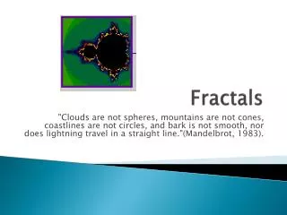
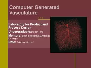
Cerebral Vasculature and Fractals. Week 12. Smit Naik Advisor: Brian Sweetman Director: Andreas Linninger LPPD UIC Spring 2009. Purpose and Motivation. Define cerebral vasculature quantitatively. Arteries ArteriolesCapillariesVenulesVeins

E N D
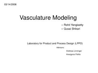
Cerebral Vasculature and Fractals Week 12 Smit Naik Advisor: Brian Sweetman Director: Andreas Linninger LPPD UIC Spring 2009
Purpose and Motivation • Define cerebral vasculature quantitatively. • ArteriesArteriolesCapillariesVenulesVeins • Simulate fluid flow through vasculature given quantified parameters and constraints. • Predict vasculature response.
Goals • Further understand and create fractals using programming software (Matlab). • Experiment with algorithms to create possible microvasculature architecture.
PseudoCode/Results Matrix Store New Segment = n x 5 matrix = [order element x y z] = Designate Initial Parameters [ … 8 90 34.9966 27.5478 1.2586 8 90 35.0896 27.6099 1.2537 5 0 35.5251 27.8744 2.0727 5 91 36.3048 28.3572 2.4317 5 91 37.0767 28.8299 2.4976 5 91 37.8566 29.2937 2.5667 5 91 38.6483 29.7474 2.6615 5 91 39.4559 30.1863 2.8224 5 91 40.2742 30.6017 3.0683 9 0 36.4416 28.4078 2.7170 9 92 36.4873 28.4278 2.7690 9 92 36.5331 28.4478 2.8208 … ] Find New Segment Element Draw/Store New Segment Find Parameters Of Initial Point on Next Element Print final values
Random Generation • Used similar parameters as University of Washington2 paper. • Dimensions used were based on:
Randomization of Number of Segments and Segment Length in 2 Dimensions • All models have: • same initial element • 150 total branches • Same possible element parameters as designated by Washington2
3-Dimensional Parameters • Volume is designated • 60x60x10 slab • Orders 1, 2, 3, and 4 remain on surface of slab (remain 2-dimensional). • Orders 5+ penetrate into surface. • Self- and boundary-avoidance parameters are maintained.
End Result - Sparse (b) (a) 100 total branches. Red are branches of order 1-4. Blue are of order 5. Magenta are of order 6-7. Black are of order 8+. (a) Top View (b) Side View (c) Angled view (c)
End Result - Dense Boundary – 60x60x10 1000 branches (60x60x30 window) 2000 branches (60x60x60 window)
Conclusions/Future Work • Create different boundary parameters based on mesh triangles. • Rather than 6 boundaries of cube, there will be many boundaries to take into account. Closest point to plane