Transformer Seminar
Transformer Seminar. BASIC THEORY BONDING AND GROUNDING OVERVIEW GENERAL PURPOSE TRANSFORMERS. Basic Transformer. Voltage Transformation. Turns Ratio. Voltage Ratio. Three Basic Components. Core (magnetics) Coils (conductors) Insulation (paper, etc.) .

Transformer Seminar
E N D
Presentation Transcript
Transformer Seminar BASIC THEORY BONDING AND GROUNDING OVERVIEW GENERAL PURPOSE TRANSFORMERS
Three Basic Components • Core (magnetics) • Coils (conductors) • Insulation (paper, etc.)
Electrical Types, cont’d “SHIELDED ISOLATION”
Bonding and Grounding Overview • All dead metal parts in an electrical system must be grounded per the NEC. • This includes the metal enclosure of a transformer. • It should be grounded to the source ground! • This insures that fault current is safely carried back to the source overcurrent device.
When installing an “isolation transformer” the output voltage will be “floating” or “isolated” from the supply voltage and from ground. • An isolation transformer produces what the NEC refers to as a separately derived service. • It also states that in this case you can now “bond” any point of the transformer output to “ground”. • If left “floating” to ground no stable or fixed voltage measurements to ground can be obtained. • A floating output will prevent any GFCI devices from operating.
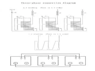
Let’s now examine a typical single phase isolation transformer installation and discuss various options for bonding the output to ground. • In this example we will use a unit with a 240 X 480 primary and a 120/240 secondary. • This means the input or supply voltage can be either 240 volts or 480 volts. • The output voltage can be either 120 volts, 240 volts, or both 120 and 240 volts at the same time.
Typical Diagram • For 120 volt only connect: X1 to X3 and X2 to X4. • You would measure 120 v across the two pairs but there is no ground reference yet. • The NEC would consider both output wires “hot” and would require overcurrent protection in both wires. • If we bond or ground one of these output wires it then becomes “neutral” and no longer requires overcurrent protection. • Once the neutral is bonded now any GFCI device on this 120 v output will operate.
For 120/240 output connect: X2 to X3 to make the neutral. • Connect one leg of 240 v to X1. • Connect one leg of 240 v to X4. • You would measure 240 v between X1 and X4 and measure 120 v between X1 and neutral and also X4 to neutral. • As stated earlier the neutral (X2 and X3) would be considered “hot” unless it were bonded to ground. • Unbonded neutral would require overcurrent protection. • GFCI devices will not operate unless the neutral is bonded to ground.
How can you tell if the neutral in any electrical system is bonded to ground or not? Answer: If the neutral has been bonded to ground then the voltage between neutral and ground will read “Zero” volts.