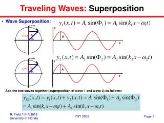

Superposition Theorem
E N D
Presentation Transcript
Superposition Theorem Superposition theorem is one of the important method that takes a complex circuit and simplifies it in a way that makes a perfect sense and make that circuit a simple one and easy to understand. Superposition theorem helps to analyze a complex circuit with multiple sources to determine the net current/voltage in a desire component when all sources are connected
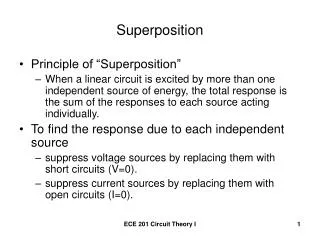
Superposition Theorem……… • The strategy used in the Superposition Theorem is to eliminate all but one source of power within a network at a time, using series/parallel analysis to determine voltage drops and/or currents within the modified network for each power source separately.
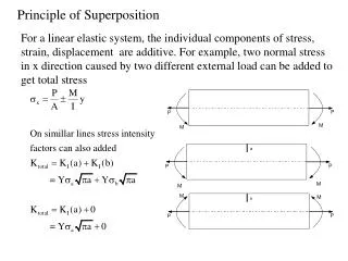
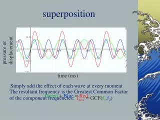
Superposition Theorem……… • Then, once voltage drops and/or currents have been determined for each power source working separately, the values are all “superimposed” on top of each other (added /subtracted algebraically) to find the actual voltage drops/currents with all sources active at a time. • Let's look at our example circuit again and apply Superposition Theorem to it:
Superposition Theorem……… Since we have two sources of power (28V and 7V) in this circuit, we will have to calculate two sets of values for voltage drops and/or currents flowing through each component, one for the circuit with only the 28 volt battery in effect and other with the 7 volt battery in effect . . .
Superposition Theorem………Analysis when B1 is connected and B2 is replaced by its equivalent. Analyzing the circuit with only the 28 volt battery, we obtain the following values for voltage and current:
Complete mathematical analysis for 28 Volt battery when 7volts battery is short. R2 || R3 = 2 || 1 = 0.667 RT = R1 + (R2 || R3) = 4 + 0.667 = 4.667 IT = VT / RT = 28V / 4.667 = 5.99A 6A V1 = I1 * R1 = 4 * 6A = 24V Using Current Divider Rule we can calculate the branch currents I2 and I3 as follows: I2 = (R3 / (R2 + R3)) * IT = (1 /3) * 6A = 2A I3 = (R2 / (R2 + R3)) * IT = (2 /3) * 6A = 4A
Superposition Theorem……… Now V2 and V3 can be calculated by using Ohm’s Law as: V2 = I2 * R2 = 2A * 2 = 4V and V3 = I3 * R3 = 4A * 1 = 4V V2 = V3 (because R2 || R3) and IT = I1 = I2 + I3 = 2A + 4A = 6A and finally VT = V1 + (V2 = V3) = 24V + 4V = 28V
Superposition Theorem………Analysis when B2 is connected and B1 is replaced by its equivalent. When re-drawing the circuit for series/parallel analysis with one source, all other voltage sources are replaced by wires (shorts), and all current sources with open circuits (breaks). Since we only have voltage sources (batteries) in our example circuit, we will replace every inactive source during analysis with a wire.
Complete mathematical analysis for 7 Volt battery when 28volts battery is short. R2 || R1 = 2 || 4 = 1.333 RT = R3 + (R2 || R1) = 1 + 1.333 = 2.333 IT = VT / RT = 7V / 2.333 = 3.00A V3 = IT * R3 = 3A * 1 = 3V Using Current Divider Rule we can calculate the branch currents I1 and I2 as follows: I1 = (R2 / (R1 + R2)) * IT = (2 /6) * 3A = 1A I2 = (R1 / (R1 + R2)) * IT = (4 /6) * 3A = 2A
Now V1 and V2 can be calculated by using Ohm’s Law as:V1 = I1 * R1 = 1A * 4 = 4V and V2 = I2 * R2 = 2A * 2 = 4VV1 = V2 (because R1 || R2) and IT = I3 = I1 + I2 = 1A + 2A = 3Aand finally VT = V3 + (V1 = V2) = 3V + 4V = 7V
Important point: • When superimposing these values of voltage and current, we have to be very careful to consider polarity of each (voltage drop) and direction of current (electron/hole flow), as the values have to be algebraically added or subtracted depending upon the direction of current.
Applying these superimposed voltage figures to the circuit, the end result looks something like this:
Currents add up algebraically as well, and can either be superimposed as done with the resistor voltage drops, or simply calculated from the final voltage drops and respective resistances (I =E/R). • Either way, the answers will be the same. Here I will show the superposition method applied to current:
Once again applying these superimposed figures to our circuit:
Superposition Theorem……… • Quite simple and elegant, don't you think? • It must be noted, though, that the Superposition Theorem works only for circuits that are reducible to series/parallel combinations for each of the power sources at a time. • Thus, this theorem is useless for analyzing an unbalanced bridge circuit), and it only works where the underlying equations are linear (no mathematical powers or roots). • The requisite of linearity means that Superposition Theorem is only applicable for determining voltage and current, not power!!!
Superposition Theorem……… • Power dissipations, being nonlinear functions, do not algebraically add to an accurate total when only one source is considered at a time. • The need for linearity also means this Theorem cannot be applied in circuits where the resistance of a component changes with voltage or current. • Hence, networks containing components like lamps (incandescent or gas-discharge) or varistors could not be analyzed.
Superposition Theorem……… • Another prerequisite for Superposition Theorem is that all components must be “bilateral”, meaning that they behave the same with electrons flowing either direction through them. • Resistors have no polarity-specific behavior, and so the circuits we've been studying so far all meet this criterion.
Superposition Theorem……… • The Superposition Theorem finds use in the study of alternating current (AC) circuits, and semiconductor (amplifier) circuits, where sometimes AC is often mixed (superimposed) with DC. • Because AC voltage and current equations (Ohm's Law) are linear just like DC, we can use Superposition to analyze the circuit with just the DC power source, then just the AC power source, combining the results to tell what will happen with both AC and DC sources in effect. • For now, though, Superposition will suffice as a break from having to do simultaneous equations to
Review……. • The Superposition Theorem states that a circuit can be analyzed with only one source of power at a time, the corresponding component voltages and currents algebraically added to find out what they'll do with all power sources in effect. • To negate all but one power source for analysis, replace any source of voltage (batteries) with a wire; replace any current source with an open (break).
Question Answer