Download
1 / 54
540 likes | 714 Views
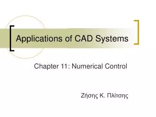
Applications of CAD Systems. Chapter 11: Numerical Control Ζήσης Κ. Πλίτσης. Computerized process planning without human intervention realized by adding Numerical Control (NC) capabilities to machine tools.

E N D
Applications of CAD Systems Chapter 11: Numerical Control Ζήσης Κ. Πλίτσης
Computerized process planning without human intervention realized by adding Numerical Control (NC) capabilities to machine tools. Numerical Control refers to the use of coded numerical information in the automatic control of equipment positioning and have to do with motion (of cutting tools or the part against a rotating tool), positioning, inserting etc. The production steps stored in a Part Program.
Περιεχόμενα • Introduction • Hardware Configuration of an NC Machine Tool • Types of NC System • NC/CNC/DNC • Basic Concepts for Part Programming • Manual Part Programming • Computer Assisted Part Programming
Περιεχόμενα • Introduction • Hardware Configuration of an NC Machine Tool • Types of NC System • NC/CNC/DNC • Basic Concepts for Part Programming • Manual Part Programming • Computer Assisted Part Programming
Introduction / History In 1940s John Parsons devised a method for manufacture of smooth shapes, relied on recording the location of the center of large number of holes and feeding this information to a machine tool to drive the cutter. The Air Corps was impressed by the idea and the task was subcontracted to the Servomechanisms Laboratory of MIT In 1952 a modified 3-axis Cincinnati Hydrotel milling machine was demonstrated by MIT, the term numerical control was coined
Introduction According to Electronic Industries Association (EIA): “Numerical Control is a system in which actions are controlled by direct insertion of numerical data at some point. The system must automatically interpret at least some portion of this data.” The part program is a set of statements that a machine control system can interpret and converted them into signals that move the spindles and drive the machine tool Today the part program can be generated directly from the CAD database by NC software and then can be the input for a NC machine tool
Περιεχόμενα • Introduction • Hardware Configuration of an NC Machine Tool • Types of NC System • NC/CNC/DNC • Basic Concepts for Part Programming • Manual Part Programming • Computer Assisted Part Programming
Hardware Configuration of an NC Machine Tool The MCU includes • the Data Processing Unit (DPU) and • the Control Loop Unit (CLU) A typical NC machine tool contains the Machine Control Unit (MCU) and the machine tool itself.
Hardware Configuration of an NC Machine Tool • DPU reads the part program, decodes it, processes the information and passes it to the CLU • CLU convert the information to control signals and drives the mechanism, receives feedback (about position and velocity) and instructs DPU to read new instructions Axis of a machine tool is defined as a path along which relative motion between the cutting tool and the workpiece occurs and a machine can have more than one axis.
Περιεχόμενα • Introduction • Hardware Configuration of an NC Machine Tool • Types of NC System • NC/CNC/DNC • Basic Concepts for Part Programming • Manual Part Programming • Computer Assisted Part Programming
Types of NC System Used • Point-to-Point NC controllers – PTP When the path of the tool relative to the work piece is not important, maybe when the tool is not in contact with the workpiece • Contouring (continuous) NC systems When the motion of the tool relative to the part being machined is important
Περιεχόμενα • Introduction • Hardware Configuration of an NC Machine Tool • Types of NC System • NC/CNC/DNC • Basic Concepts for Part Programming • Manual Part Programming • Computer Assisted Part Programming
NC/CNC/DNC • Third generation of machine tools uses integrated circuits and memory technology wildly used in computer hardware • Computer Numerical Control (CNC, about 1970) program needs loading into the MCU once, the controller resembles a personal computer, it is a special-purpose computer for control of machine tools with CPU, ROM, RAM, hard disk communication ports, key pad, display monitor etc. • Today PC-based NC are available which use general-purpose PC with servo-control board.
NC/CNC/DNC • Direct Numerical Control is a system that uses a central computer to control several machines at the same time • Distributed Numerical Control (DNC): the central computer downloads complete programs to the CNC machines, which can be workstations or PCs, and can get the information for the machine operations. The speed of the system is increased, large files can be handled and the number of machine tools used is expanded.
Περιεχόμενα • Introduction • Hardware Configuration of an NC Machine Tool • Types of NC System • NC/CNC/DNC • Basic Concepts for Part Programming • Manual Part Programming • Computer Assisted Part Programming
Basic Concepts for Part Programming Part programming contains geometric information about the part and motion information to move the cutting tool with respect to the workpiece The first thing to be defined is the Coordinate System and then some-one can continue with the Syntax of Part Programming
Coordinate System Main 3 Axes forming a right-hand coordinate system, by convention z axis moves the cutting tool away from the workpiece, in details: The z axis, parallel to the spindle for rotating workpiece, and parallel to the machine tool axis for rotating tool, as a milling, drilling, or boring machine The x axis, in the direction of the tool movement for the first case, and points to the right when some-one is facing the machine.
Coordinate System There can be more axes because of secondary slide motions in addition to the primary x, y and z directions, and the rotary motions around axes parallel to x, y and z axes. These axes can be labeled u, v and w (for the first case) and a, b and c (for the second). The machine tools can be classified according to the number of axes they provide to control position and orientation. For example, there are 2-axis, 3-axis and 5-axis milling machines.
Syntax of Part Programming • Various formats and well defined syntax with variations due to differences between machines • Use of a sequence of blocks containing commands to set machine parameters as speed etc • Each command has an identifying letter followed by an associated number
Syntax of Part Programming Some identifying letters for the commands: • Sequence number (N code) • Preparatory command (G code) • Dimension words (X, Y, Z, A and B words) • Feed commands (F code) • Speed commands (S code) • Tool selection (T code) • Miscellaneous (M code)
Syntax of Part Programming Formats for the commands arranged to form a block: • Fixed sequential format • Block address format • Tab sequential format • Word address format • For example: N040 G00 X0 Y0 Z300 T01 M06 N: identifier number, G: preparatory commands, X,Y and Z: coordinates along the x, y and z axis T: the tool number and M: miscellaneous commands
Περιεχόμενα • Introduction • Hardware Configuration of an NC Machine Tool • Types of NC System • NC/CNC/DNC • Basic Concepts for Part Programming • Manual Part Programming • Computer Assisted Part Programming
Manual Part Programming Part program manuscript
Manual Part Programming Answer: N001 G91 EOB N002 G71 EOB N003 G00 X0.0 Y0.0 Z40.0 T0.1 M06 EOB N004 G01 X65.0 Y0.0 Z-40.0 F950 S717 M03 EOB N005 G01 X10.0 F350 M08 EOB N006 G01 X110.0 EOB N007 G01 Y70.0 EOB N008 G01 X-40.86 EOB N009 G02 X-28.28 Y0.0 I14.14 J5.0 EOB N010 G01 X-40.86 EOB N011 G01 Y-70.0 EOB N012 G01 X-75.0 Y0.0 Z40.0 F950 M30
Περιεχόμενα • Introduction • Hardware Configuration of an NC Machine Tool • Types of NC System • NC/CNC/DNC • Basic Concepts for Part Programming • Manual Part Programming • Computer Assisted Part Programming
Computer Assisted Part Programming The alternative to manual part programming is the use of high-level programming language, which: • Defines the geometry part in terms of basic geometry elements (points, lines …) • Instructs the machine about the cutting tool
Computer Assisted Part Programming So the following procedures must be used to obtain the G-code: • The programmer identifies the part geometry, cutter motions, feeds, speeds and cutter parameters • The programmer codes the part geometry, cutter motion, feed etc and this is the source using a programming language • The source is then compiled to produce the machine independent list of cutter movements and other machine control information (the cutter location control data file or CL data file) • The CL data are processed by post-processor to generate machine control data for the particular machine
APT Language The most comprehensive and widely used language is Automatically Programmed Tool (APT) – the first prototype of the APT system was developed at MIT in 1956. The APT statements belong to one of the five types: • Identification statements • Geometry statements • Motion statements • Post-processor statements • Auxiliary statements
APT Language Geometry statements, the general form of geometry statement is: Symbol = geometry_word/descriptive data • In the case of points: P1 = POINT/X, Y, Z P2 = POINT/L1, L2 P3 = POINT/CENTER, C1 P4= POINT/YLARGE, INTOF, L1, C1 P5= POINT/XLARGE, INTOF, L1, C1 P6= POINT/XLARGE, INTOF, C1, C1 P7= POINT/YLARGE, INTOF, C1, C1
APT Language • In the case of lines: L1 = LINE/X1, Y1, Z1, X2, Y2, Z2 L2 = LINE/P1, P2 L3 = LINE/P1, PARLEL, P2 L4 = LINE/P1, PERPTO, L0 L5 = LINE/P1, LEFT, TANTO, C1 L6 = LINE/P1, RIGHT, TANTO, C1 L7 = LINE/LEFT, TANTO, C1, LEFT, TANTO, C2 L8 = LINE/LEFT, TANTO, C1, RIGHT, TANTO, C2 L9 = LINE/RIGHT, TANTO, C1, LEFT, TANTO, C2 L10 = LINE/RIGHT, TANTO, C1, RIGHT, TANTO, C2 L11 = LINE/P1, ATANGL, L0
APT Language • In the case of circles: C1 = CIRCLE/X, Y, Z, R C2 = CIRCLE/CENTER, P1, RADIOUS, R C3 = CIRCLE/CENTER, P1, TANTO, L0 C4 = CIRCLE/P1, P2, P3 C5 = CIRCLE/XSMALL, L1, XSMALL, L2, RADIOUS, R …And the same with XLARGE, YLARGE or YSMALL • In the case of planes: PL1 = PLANE/P1, P2, P3 PL2 = PLANE/PARLEL, PL0, XLARGE, D …And the same with XLARGE, YLARGE, YSMALL, ZLARGE or ZSMALL
APT Language Motion statements, with regard to point-to-point operation there are three motion statements for positioning the tool at a desired point: • FROM/point_location • GOTO/point_location • GODLTA/Δx, Δy, Δz
APT Language Answer: P0 = POINT/0.0, 3.0, 0.1 P1 = POINT/1.0, 1.0, 0.1 P2 = POINT/2.0, 1.0, 0.1 FROM/P0 GOTO/P1 GODLTA/0, 0, -0.7 GODLTA/0, 0, 0.7 GOTO/P2 GODLTA/0, 0, -0.7 GODLTA/0, 0, 0.7 GOTO/P0
APT Language Other Motion statements: • GO/{TO}, Drive surface, {TO} Part surface, {TO}, Check surface Or • GO/{TO}, Drive surface, {TO} Part surface, {TANTO}, Check surface …And the same with PAST or ON instead of TO • GOLFT/ • GORGT/ • GOUP/ • GODOWN/ • GOFWD/ • GOBACK/ For example: GO/TO, L1, TO, PS, TANTO, C1 GO/PAST, L1, TO, PS, TANTO, C1
APT Language Answer: FROM/SP GO/TO, L1, TO, PS, ON, L4 GORGT/L1, PAST, L2 GOLFT/L2, PAST, L3 GOLFT/L3, PAST, C1 GOLFT/C1, PAST, L3 GOLFT/L3, PAST, L4 GOLFT/L4, PAST, L1 GOTO/SP
APT Language Answer: FROM/SP GO/TO, L1, TO, PS, ON, L6 GORGT/L1, PAST, L2 GORGT/L2, TANTO, C1 GOFWD/C1, TANTO, L3 GOFWD/L3, PAST, L4 GOLFT/L4, PAST, L5 GOLFT/L5, PAST, L6 GOLFT/L6, PAST, L1 GOTO/SP
APT Language Additional statements: • MACHIN/DRILL, 2 • COOLNT/ For example:COOLNT/MIST COOLNT/FLOOD COOLNT/OF • FEDRAT/ • SPINDL/ For example:SPINDL/ON SPINDL/1250, CCLW • TOOLNO/ • TURRET/ • END
APT Language Other capabilities of APT, the macro facility, with use variable argument as in a FORTRAN subroutine, for example: P0 = POINT/0.0, 0.3, 0.1 FROM/P0 CALL/DRILL, X=1.0, Y=1.0, Z=0.1, DEPTH=0.7 CALL/DRILL, X=2.0, Y=1.0, Z=0.1, DEPTH=0.7 GOTO/P0 when the definition of the macro DRILL is: DRILL = MACRO/X, Y, Z, DEPTH GOTO/X,Y,Z GODLTA/0,0, -DEPTH GODLTA/0,0, DEPTH TARMAC
APT Language Answer (1/4): PARTNO PART11 MACHIN/MILL, 3 ;machine selection CLPRINT ;prints out CL data file OUTTOL/0.002 SP =POINT/5,0,1 P1 =POINT/1,2,0.5 P2 =POINT/4,2,0.5 P3 =POINT/6,4,0.5 P4 =POINT/8,5,0.5 P5 =POINT/9,7,0.5 P6 =POINT/2,7,0.5 PL1 = PLANE/P1, P2, P3 PS = PLANE/PARALEL, PL1, ZSMALL, 0.5 ;define part surface to be z = 0
APT Language Answer (2/4): C1 = CIRCLE/CENTER, P4, RADIOUS, 1.0 L1 = LINE/P2, P3 L2 = LINE/P3, RIGHT, TANTO, C1 L3 = LINE/P5, LEFT, TANTO, C1 L4 = LINE/P5, P6 L5 = LINE/P6, P1 L4 = LINE/P1, P2 MILL = MACRO/CUT, SPIN, FEED, CLNT CUTTER/CUT FEDRAT/FEED SPINDL/SPIN COOLNT/CLNT FROM/SP