Download
1 / 20
200 likes | 239 Views
In this enlightening study, Andrei Lozzi delves into the life histories of CAD vendors, highlighting the evolution of CAD systems in the marketplace. The article elucidates concepts such as orthonormal and perspective views, showcasing their significance in CAD design and engineering. Furthermore, it discusses the role of wire frame coding and programming in CAD applications, emphasizing the efficiency and precision it offers in creating detailed drawings. The narrative also touches upon the development of solid modelers and their impact on design accuracy and manufacturing processes. Additionally, the article explores nesting programs for 2D patterns, demonstrating their cost-saving benefits and waste reduction capabilities. In the realm of 3D wire frame systems, the text elucidates their advantages in visual representation and design accuracy. From the innovative use of perspective views in industrial design to the intricacies of CAD application programming, this article provides valuable insights into the diverse applications and advancements in the field of CAD.

E N D
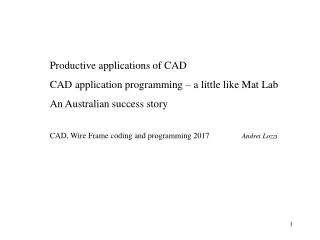
Productive applications of CAD CAD application programming – a little like Mat Lab An Australian success story CAD, Wire Frame coding and programming 2017Andrei Lozzi
The life histories of CAD vendors The are many players in CAD. Most have had a lifetime of ~ 20 years. They get bigger and bigger then collapse. Generally the packages are getting better and cheaper. CAD systems have typically had similar history on the marketplace. These have been highlighted by a slow raise followed by other raises as the software is developed. Finally a time is reached when some competitor has a significantly better package
Orthonormal – 2D projections Ortho-normal projections, are projections where the visible outlines and edges of an object, are projected perpendicularly to the drawing sheet. This gives a line drawing that is ‘correct to size and shape’. That is it has the linear dimensions (maybe scaled) and angles of the item. On such drawings instructions can be precisely given on the work to be carried out and of the dimensions of item. 2D or 3D line drawing programs can do these drawings easily but cannot give pictorial or perspective drawings directly. 3D lines and surfaces packages can but with a lot of work. Solid modellers provide the pictorial presentations first then the orthogonal drawings automatically by deduction.
Perspective or Pictorial views A pictorial view, picture-like, maybe a perspective dwg or something simpler, makes the subject look realistic. The viewer can more readily comprehends the relationship of the parts to the whole. They can more quickly deduce how it may function, because it may look like similar items that the engineer is familiar with. This leads to fewer mistakes in handling. If little or no effect of perspective is shown then the parts are small. But significant perspective effect is present, then it indicates that the parts are large, like buildings. It is difficult if not impossible on such drawings to give exact information on the dimensions and method of manufacture. Pictorial drawings tend to be used to create subjective impressions not objective ones.
The quickest or cheapest drawings are sometimes done by automated programs not operators. Here is the output of a program that records the physical details of a plain slide bearing (as used in nearly all engines). A specialised manufacturer may have 20 000 detail drawings like these, their records must be complete and precise to deal with errors and developments
Nesting programs for 2D patterns, are often an application of a CAD system that can justify just by itself, the purchase and all other applications of a CAD package. This operation may result in the reduction of waste by something like a minimum of 10% of the stock which annually may cost $20M
3D Wire Frame systems began to establish their advantages where it is important to determine what was may be visible and what may be not, like this simulated view from a seat in the Sydney Entertainment Centre. All done in with lines only, no surfaces and note the approximation to curves by short straight line segments. This system was developed by some grads from our Civil dept. This team had set out to extend their system to solid modelling.
Prior to the adoption of solid modellers, a process plant shown at left would be initially modelled in wood. The erection and assembly would be done progressively, the main parts first then the valves and e pipes and elbows would be cut and welded on site. An example of such a model is in the foyer of the Chemical Engineering Building, level 2. With the use of a precise reliable CAD system all parts are made off site, with minimal adjustments on site.
Multi point perspective - by a 3D wire-frame & surfaces CAD Perspective views of a fruit harvester. These views began as 1000s of 2D orthographic drawings of parts. One of our UGs (while working over summer) assembled them in space, added surfaces, removed hidden lines, generating the views shown. Each took many hours of computer time. The company was unaware of this capability of their system. They used them in training, operating manuals and sales brochures. The moral: if you do not keep abreast you get left behind
CAD application programming can be done at many levels. Macros - By recording and editing the commands an operator enters at the terminal, forming macro command files. There may be 30k such instructions in SW Sub interface - By using the commands that the user interface relies on, commands that instruct the kernel. There may be 2-3k such instructions. These may be in c or basic, compiled or interpreted. Deep - By using the operations that the kernel itself uses, at this level there may be only a few hundreds instructions but many may have to used for each simple action. These may be in c or assembler and will require compilation.
Applications where no drawing is made. A sheep shearing robot. The computer works on a generalised shape of a sheep. The shearing begins on the simplest surface, that is the back, as this progresses the appropriate size and proportions of the particular sheep are determined. Progressively the increasingly more difficult parts of the sheep are calculated for and modelled and then shaved. All this while the sheep is trying to meditate.
Engineering analysis and drawing applications. There are a huge number of engineering software that assist it arriving at the shape of a component by dealing with the functional requirements of the part and then the stresses that come from the function. Like the shape of the wing section of a propeller that will give the required thrust, thence the stresses that that propeller will generate.
p - Perpendicular distance from centre to the line of the force Centre of bolt pattern F - Force Example of CAD program application doable by students. A force has to be resisted and a bolt pattern of 5 bolts is nominated to do the task. The bolts have to resist a torque equal to f X p and a shear force F acting on the pattern.
F F/5 From here on, to simplify the drawing, only the effect on 3 bolts will be shown. The force F is shared equally by all bolts, ie each take F/5. Note forces and torques are vectors
p F r ft Here the effect of the torque F X p (F cross product p) is distributed between the bolts. The force on each bolt due to the torque - ft is shown perpendicular to the radius r from the centre of the bolt pattern.
The effect of the torque is divided unequally among the bolts. The torque tries to rotate the plates w.r.t. each other hence the bolts furthest away from the centre try to move the most. A bolt at the centre does not share in the torque load.
fr3 fr2 fr1 Each bolt take the vector sum of these 2 force components worked out above fri. The resulting force on each bolt can have very different magnitudes, eg fr1> fr3> fr2. Usually a bolt is chosen of a diameter and grade to take the largest load, then that type of bolt is used everywhere. Some bolts are as result underutilised. Some bolt pattern are better than others at sharing the load more equally.
An example of a Revolutionary CAD application Allco a structural steel company (used to be in Tomago) could order the stock lengths of steel from BHP that assured minimal waste. From the stores on the far left the sections were passed to the cutting machines at the left end of the sheds. Left overs had to be returned to the store pile and were almost eliminated. The saving in waste alone paid for the CAD system and personnel. The steel structure at Darling Harbour and Grosvenor Place are examples of their work.
Designers could select the type of sections and how they were to be connected from a library of standard connections. How the sections were to be joined would depend on the magnitude of the moment and shear forces at the joint and wether they were to be welded or bolted. Although drawings could be prepared they were seldom required, in the factory computer screens were used. Nearly all the work was done on site by NC machines and welding robots. The lengths to be cut and end preparations, such as drilling and welding, took the form of digital instructions.
Allco P/L in the 80s developed an extensive 3D wire frame package that could arrive at all the major components and operations that would be needed to make the frame of a building. This could be done in few days work. This gave them a huge advantage in competing for contracts by giving them a better estimate of costs and work involved. they could leave the unprofitable contracts to their competitors. BUT, within a few years software developers with bigger markets had develop comparable if not better systems. Allco had to decide wether to continue to develop theirs or take up some else’s product, which would no longer give them an individual advantage This stepwise development of software is typical in all applications.