Download
1 / 23
300 likes | 1.44k Views
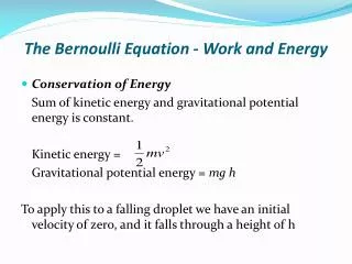
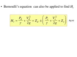
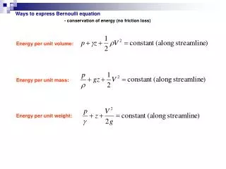
Ways to express Bernoulli equation . - conservation of energy (no friction loss). Energy per unit volume:. Energy per unit mass:. Energy per unit weight:. Civil Engineers often use the “energy per unit weight” form:. is often referred to as total head.

E N D
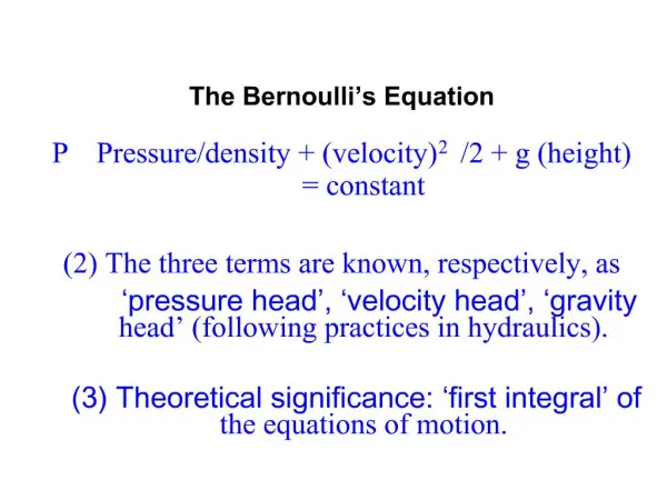
Ways to express Bernoulli equation - conservation of energy (no friction loss) Energy per unit volume: Energy per unit mass: Energy per unit weight:
Civil Engineers often use the “energy per unit weight” form: is often referred to as total head is often referred to as pressure head is often referred to as elevation (or potential) head is often referred to as velocity head
Mechanical engineers often use the “energy per unit volume” form: is often referred to as total pressure is often referred to as staticpressure is often referred to as hydrostatic pressure is often referred to as dynamic pressure
Pressure measurements (static, dynamic and stagnation pressure) Consider the following closed channel flow (neglect friction): open open pitot tube 5 piezometer tube 4 1 2 Uniform velocity profile Velocity at point 1 is the velocity of the flow: Point 2 is at the entrance of the pitot tube where velocity is zero
Pressure measurements (static pressure) pitot tube 5 piezometer tube 4 1 2 To measure static pressure say at point 1 we use piezometer tube along with p + γz = constant across straight streamlines between pts. 1 and 4:
Pressure measurements (dynamic pressure) pitot tube 5 piezometer tube 4 1 2 To measure dynamic pressure say at point 1 we use pitot tube along with Bernoulli equation from point 1 to point 5:
Pressure measurements (dynamic pressure) pitot tube 5 piezometer tube 4 1 2
Pressure measurements (dynamic pressure) pitot tube 5 piezometer tube 4 1 2
Pressure measurements (dynamic pressure) pitot tube 5 piezometer tube 4 1 2
Pressure measurements (stagnation pressure (pressure at pt. 2)) pitot tube 5 piezometer tube 4 1 2 Stagnation pressure is pressure where velocity is zero (at entrance of pitot tube (pt. 2))
Pressure measurements (stagnation pressure (pressure at pt. 2)) pitot tube 5 piezometer tube 4 1 2 Stagnation pressure is pressure where velocity is zero (at entrance of pitot tube (pt. 2)) Bernoulli from pt. 1 to pt. 2:
Pressure measurements (stagnation pressure (pressure at pt. 2)) pitot tube 5 piezometer tube 4 1 2 Stagnation pressure is pressure where velocity is zero (at entrance of pitot tube (pt. 2)) Bernoulli from pt. 1 to pt. 2:
Pressure measurements (stagnation pressure (pressure at pt. 2)) pitot tube 5 piezometer tube 4 1 2 Stagnation pressure is pressure where velocity is zero (at entrance of pitot tube (pt. 2)) Bernoulli from pt. 1 to pt. 2: Stagnation pressure at pt. 2 is:
Pressure measurements Stagnation pressure Static pressure Note that Airplanes use pitot-static tubes (a combination of piezometer and pitot tubes) to measure p2and p1and compute airplane speed using previous equation
Energy Grade Line (EGL) and Hydraulic Grade Line (HGL) Graphical interpretations of the energy along a pipeline may be obtained through the EGL and HGL: EGL and HGL may be obtained via a pitot tube and a piezometer tube, respectively In our discussion we will be taking atmospheric pressure equal to zero, thus we will be working with gage pressures
Energy Grade Line (EGL) and Hydraulic Grade Line (HGL) • head loss, say, • due to friction EGL HGL piezometer tube pitot tube Datum
Energy Grade Line (EGL) and Hydraulic Grade Line (HGL) EGL Large V2/2g because smaller pipe here HGL Steeper EGL and HGL because greater hL per length of pipe Head loss at submerged discharge
Energy Grade Line (EGL) and Hydraulic Grade Line (HGL) Positive Negative Positive EGL HGL If then and cavitation may be possible
Energy Grade Line (EGL) and Hydraulic Grade Line (HGL) Helpful hints when drawing HGL and EGL: 1. EGL = HGL + V2/2g, EGL = HGL for V=0 2. If p=0, then HGL=z 3. A change in pipe diameter leads to a change in V (V2/2g) due to continuity and thus a change in distance between HGL and EGL 4. A change in head loss (hL) leads to a change in slope of EGL and HGL 5. If then and cavitation may be possible
Helpful hints when drawing HGL and EGL (cont.): 6. A sudden head loss due to a turbine leads to a sudden drop in EGL and HGL 7. A sudden head gain due to a pump leads to a sudden rise in EGL and HGL 8. A sudden head loss due to a submerged discharge leads to a sudden drop in EGL
Hydrostatic Paradox At Lake Mudd and Lake Mead, the depth is ~600 ft. At Lake Mead, the horizontal thrust near the base of the dam is ~18 tons per square foot. Here is the paradox: in both cases, the horizontal thrust on the dam is the SAME
Hydrostatic Paradox The reason for this paradox is that the pressure depends only on the depth of the water, not on its horizontal extent:
Hydrostatic Paradox See movie at:http://www.ac.wwu.edu/~vawter/PhysicsNet/QTMovies/PressureFluids/HydrostaticParadoxMain.html