Bernoulli Applications
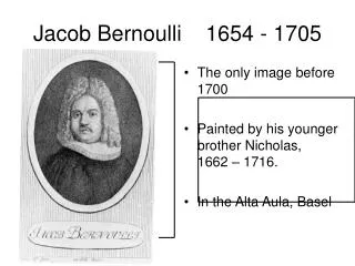
Bernoulli Applications . Venturi Meter. A Venturi meter is used to measure the flow rate through a tube. It is based on the use of the Venturi effect, the reduction of fluid pressure that results when a


Bernoulli Applications
E N D
Presentation Transcript
Venturi Meter • A Venturi meter is used to measure the flow rate through a tube. • It is based on the use of the Venturi effect, the reduction of fluid pressure that results when a • fluid runs through a constricted section of pipe. It is called after Giovanni Battista Venturi (1746-1822), • an Italian physicist. • Look at the construction in figure: • we assume the flow is smooth and • effectively inviscid, ie. friction is • negligible. • the fluid is incompressible, and has • density throughout the pipe. • downstream we have a flow through • a pipe section of area A1, with a • flow velocity v1, and pressure p1. • in the narrow section with area A2, • the fluid flows with flow speed v2, • and has accomanying pressure p2. • as a result the two meters • indicate the difference in pressure • by means of a height difference h.
Venturi Meter To find the pressure difference between the downstream flow and the pipe narrow, we invoke 1) the Bernoulli theorem and 2) the continuity equation. The latter assures that the rate of fluid flow through any section remains constant, ie. mass is preserved. Bernoulli Theorem: as the flow is horizontal, we do not have to take into account the gravity term. Continuity equation: Combining both equations, we find for the pressure difference in the two parts of the pipe:
Venturi Meter To read of the pressure difference between the two locations 1 and 2 in the fluid, we use the height difference h between the fluid level in the vertical tubes. To connect this height difference h to the pressure difference p1 and p2, we invoke the Euler equation: Euler equation (for a static medium): With the outside atmosphere pressure being Patm, we then directly infer for the pressure P1 and p2, From this we may then infer the flow velocity v1 (as well as v2):
Air Flow along Wing airflow along the wing of an airplane: note the condensation over the upper part of the wing, where the higher flow speeds corresponds to a lower pressure and thus lower temperature.
Air Flow along Wing One of the most interesting applications of the Bernoulli equation, is the flight of aeroplanes. Here we will provide a simplified explanation, based on the Bernoulli equation (reality is somewhat more complex). Aeroplanes can fly because of the pressure difference between the flow below the wing and the flow over the wing*. This pressure difference results in a lift force that opposes the weight of the aeroplane (note that similar lifting forces work on many different objects, eg. wings of mills or wind turbines, sails on a sailboat, propellors). Forces working on a wing – airfoil. Flow around an airfoil: the dots move with the flow. Note that the velocities are much higher at the upper surface than at the lower surface. The black dots are on timelines, which split into two — an upper and lower part — at the leading edge. The part of a timeline below the airfoil does not catch up with the one above ! Colors of the dots indicate streamlines. • Jet fighters often are not kept aflight by • Bernoulli. Instead, they have the thrust • of the jet motor, with vertical component, • to keep them in the air.
Air Flow along Wing One of the most interesting applications of the Bernoulli equation, is the flight of aeroplanes. Here we will provide a simplified explanation, based on the Bernoulli equation (reality is somewhat more complex). Aeroplanes can fly because of the pressure difference between the flow below the wing and the flow over the wing*. This pressure difference results in a lift force that opposes the weight of the aeroplane (note that similar lifting forces work on many different objects, eg. wings of mills or wind turbines, sails on a sailboat, propellors). According to Bernoulli, the Bernoulli function B is constant along any streamline. Thus, for a horizontally flying plane, we have that 1) 2) (Continuity eqn.) CL is the lift coefficient, dependent on various factors, including the angle of wing wrt. air. Along the wing, the flow over the upper (longer) edge of the wing has a (considerably) higher velocity uu than below the wing, ul *. As a result (Bernoulli), the pressure pl at the lower end of the wing is higher than the pressure pu at the upper end. The resulting pressure difference generates a lift force Flift The usual assumption of equal crosstime of upper and lower flow is not correct.
Air Flow along Wing With the pressure difference between lower and upper wing being the total effective lift force is, with A the “effective” planform area , and CL the lift coefficient, In other words, we need a certain speed V and planarea A to get sufficient lift force to lift a plane into the air … (see right) …
Air Flow along Wing Reality, of course, is slightly more complex. The accompanying movie gives an impression …
De Laval Nozzle Bernoulli Equation: compressible fluids. A very interesting application of the Bernoulli equation, for compressible fluids, concerns the de Laval nozzle. A de Laval nozzle is a tube that is pinched in the middle, making a carefully balanced, asymmetric hourglass-shape. The nozzle was developed in 1888 by the Swedish inventor Gustaf de Laval for use on a steam turbine. The principle was first used for rocket engines by Robert Goddard. The de Laval nozzle forms a nice platform to highlight the differences introduced by the compressibility of a gas when applying Bernoulli’s theorem.
De Laval Nozzle The de Laval nozzle is used to accelerate a hot, pressurised gas passing through it to a supersonic speed. High-pressure gas coming from the combustion chamber enters the nozzle and flows into a region where the nozzle cross section decreases, dA/dx < 0. The thermal energy is converted into kinetic energy of the flow, and the flow goes through a sonic point at the critical point where the nozzle cross section narrows to its minimum (dA/dx=0). At that point the flow speed reaches the sound velocity. The cross section increases again after the critical point, and the gas is further accelerate to supersonic speeds. The de Laval nozzle shapes the exhaust flow so that the heat energy propelling the flow is maximally converted into directed kinetic energy. Because of its properties, the nozzle is widely used in some types of steam turbine, it is an essential part of the modern rocket engine, and it also sees use in supersonic jet engines. Astrophysically, the flow properties of the de Laval nozzle have been applied towards understanding jet streams, such as observed in AGNs (see figure), the outflow from young stellar objects and likely occur in Gamma Ray Bursts (GRBs).
De Laval Nozzle If we make the approximation of steady, quasi-1-D barotropic flow, we may write Bernoulli’s theorem and the equation of continuity as where A is the local sectional area of the nozzle. Note that because of the compressibility of the gas we no longer assume a constant density, and thus have to keep in the integral. Gravitational potential variations are ignored, as for terrestrial applications the fast flow of jet gases is not relevant over the related limited spatial extent. Two illustrations of the de Laval nozzle principle. The 2nd figure is a measurement of the flow speed in an experiment.
De Laval Nozzle The variation of the area A along the axis of the nozzle will introduce spatial variations for each of the other quantities. To consider the rate of such variations, take the differential of the Bernoulli equation, Taking into account that the sound velocity cs associated with the barotropic relation is we find from the equations above that We define the Mach number of the flow as the ratio of the flow velocity to the sound velocity, Illustration of the run of flow speed u, pressure p and temperature T, as the gas passes through the nozzle and its sonic point.
De Laval Nozzle From the relation between velocity and density, we find that the fractional change of density is related to the fractional change of the fluid velocity u via the equation This equation states that the square of the Mach number provides a measure of the importance of compressibility. In particular, flow of air at subsonic speeds past terrestrial obstacles can often be approximated as occurring Incompressibility, because the fractional change of density is negligible in comparison with the fractional change of u if M1. In contrast, supersonic flight past obstacles necessarily involves substantial compressions and expansions. Illustration of the run of flow speed u, pressure p and temperature T, as the gas passes through the nozzle and its sonic point.
De Laval Nozzle To relate the change of velocity u to the change of sectional area A in the nozzle, we take the logarithmic derivative of the continuity equation, To consider the rate of such variations, take the differential of the Bernoulli equation, which, taking into account the relation between density and flow speed u, yields the following relation between u and A: Illustration of the run of flow speed u, pressure p and temperature T, as the gas passes through the nozzle and its sonic point.
De Laval Nozzle the relation has the following implications: Subsonic speeds: this corresponds to normal experience, eg. the speeding up of a river as the channel narrows. Illustration of the run of flow speed u, pressure p and temperature T, as the gas passes through the nozzle and its sonic point.
De Laval Nozzle 2) Supersonic speeds: In other words, an increase in the velocity requires an increase in the area of the nozzle, dA>0 !!! This counterintuitive result has a simple explanation: for M>1, the density decreases faster than the area increases, so the velocity must increase to maintain a constant flux of mass. Illustration of the run of flow speed u, pressure p and temperature T, as the gas passes through the nozzle and its sonic point.
De Laval Nozzle A sonic transition , ie. can be made smoothly, ie. With only at the throat of the nozzle where To obtain supersonic exhaust, therefore, we must accelerate the reaction gases through a converging-diverging nozzle, a fundamental feature behind the design of jet engines and rockets. Note that the converse does not necessarily hold: M does not necessarily equal unity at the throat of the nozzle, where dA=0. If M1, the fluid velocity reaches a local extremum when the area does, i.e. du=0 where dA=0. Whether the extremum corresponds to a local maximum or minimum depends on whether we have subsonic or supersonic flow and whether the nozzle has a converging-diverging shape. Illustration of the run of flow speed u, pressure p and temperature T, as the gas passes through the nozzle and its sonic point.
De Laval Nozzle Final Notes: 5) whether supersonic exhaust is actually achieved in nozzle flow also depends on the boundary conditions. In particular, on the pressure of the ambient medium in comparison with the pressure of the reaction chamber. If a sonic transition does occur, the flow behaviour depends sensitively on the nozzle conditions, since the coefficient 1-M2 becomes arbitrarily small near the transition region. When external body forces are present, we do not need to have a throat to achieve the smooth transition of subsonic to supersonic flow. The external forces can provide the requisite acceleration. Illustration of the run of flow speed u, pressure p and temperature T, as the gas passes through the nozzle and its sonic point.
Incompressible Flow Many problems of practical importance, involving a large number of engineering and terrestrial conditions concern incompressible flows. For an incompressible flow, we have which follows directly from the continuity equation on the basis of the conditions In other words, for an incompressible fluid (a liquid) the vairation of pressure p in the force (Euler) equation equals whatever it needs so that . Note that for an incompressible medium, Kelvin’s circulation theorem is valid independent of the barotropic assumption: because the vorticity equation is true independent of p,
Incompressible Flow • Many problems in hydrodynamics involve the motion of a solid body (eg., a ship) through • water that is stationary at infinity. • From the point of view of an observer fixed on the ship, the water flowing past • the ship originates from a steady region of uniform conditions. • Uniform flow has no vorticity: • Kelvin’s circulation then guarantees • that no vorticity will be generated • in the flow around the ship. • Note: this is only true as long as • the effect of viscosity can be • ignored. • If everywhere, • the flow field can be derived from • the gradient of a scalar, the • velocity potential
Potential Flow If we substitute the velocity potential definition into the continuity equation we obtain the condition for potential flow, This is nothing else than the Laplace equation. Thus, the solution of many problems in hydrodynamics boils down to a solution of the Laplace equation. The problem is well-posed , and there is a vast body of work on its solution. To solution of the Laplace equation is dictated by the boundary (and initial) conditions that are imposed.
Boundary Conditions To solve the Laplace equation, we need to specify the boundary conditions. There are a Variety of boundary conditions. Usually, these involve one (or more) of the following : The value of on the bounding surface of the fluid Dirichlet boundary conditions The value of its normal derivatives on the boundaries Neumann boundary conditions For the problem of a flow past a solid object like a ship or a sphere, we have the important condition that the water should not penetrate the object, ie. there should be no flow normal to its surface. This translates into the Neumann boundary condition: for the object at rest: if the object moves with velocity , then
Potential Flow To find the solutions to the Laplace equation, one can apply the mathematical machinery of potential theory. To provide an idea of the solutions we concentrate on solutions for Spherical geometry (of object) and Axisymmetric flow The general axisymmetric solution of Laplace’s equation is obtained by the separation-of-variables method in spherical polar coordinates, ie. which yields • r is the spherical radius • the co-latitude (see figure): • An and Bn are arbitrary constants, • shose value is determined by • the boundary conditions. • Pn is the Legendre Polynomial of • degree n:
I.14Potentialflow Potentialfloeisaflowinwhichthevorticityvanisheseverywhereinthefluid, i.e.,.InsuchcaseEuler'sequationcouldbewrittenas: Insuchcasethevelocitycouldbedrawnfromapotential,y,orv=∇y. Forbarotropicandpotentialforces,Euler'sequationthenbecomesvery simple. or WherefistheforcepotentialandT(t)issomefunctionoftime. 27
Hydrostatics Inhydrostaticsnoflowoccurs.Thisreducesthefluidequationstoverysimpleones Insuchacasethefluidequationsbecome: Examples: 1.Archimedes'theorem: Afluidinhydrostaticequilibriumhasauniformdensityshowthatisabodyisimmersed init,thebodyexperienceaforceequaltothegravityforceexertedonthefluidthatthe bodydisplacedandoppositeindirection. Theforcethatisexperiencedbythedisplacedfluid(priortodisplacement)bytheits surroundingsis 17
Hydrostatics Systems where motion is absent altogether, or at least has no dynamic effects, are in hydrostatic equilibrium: In those situations, the fluid equations reduce to simple equilibrium equations. Continuity equation: Euler equation: (the latter identity in the Euler equation is for the body force being the gravitational force). We will shortly address four typical examples of hydrostatic equilibrium, all of major astrophysical interest Archimedes’ Principle, bouyancy forces Isothermal sphere Stellar Structure equations 4) Mass determination of clusters from their X-ray emission. 17
Archimedes’ Principle In the situation where an object is (partially) immersed in a fluid (see figure), Archimedes’ principle states, shortly, that Buoyancy = Weight of displaced fluid Continuity equation: Euler equation: (the latter identity in the Euler equation is for the body force being the gravitational force). We will shortly address four typical examples of hydrostatic equilibrium, all of major astrophysical interest Archimedes’ Principle, bouyancy forces Isothermal sphere Stellar Structure equations 4) Mass determination of clusters from their X-ray emission. 17
Hydrostatics Inhydrostaticsnoflowoccurs.Thisreducesthefluidequationstoverysimpleones Insuchacasethefluidequationsbecome: Examples: 1.Archimedes'theorem: Afluidinhydrostaticequilibriumhasauniformdensityshowthatisabodyisimmersed init,thebodyexperienceaforceequaltothegravityforceexertedonthefluidthatthe bodydisplacedandoppositeindirection. Theforcethatisexperiencedbythedisplacedfluid(priortodisplacement)bytheits surroundingsis 17
Archimedes Principle Inhydrostaticsnoflowoccurs.Thisreducesthefluidequationstoverysimpleones Insuchacasethefluidequationsbecome: Examples: 1.Archimedes'theorem: Afluidinhydrostaticequilibriumhasauniformdensityshowthatisabodyisimmersed init,thebodyexperienceaforceequaltothegravityforceexertedonthefluidthatthe bodydisplacedandoppositeindirection. Theforcethatisexperiencedbythedisplacedfluid(priortodisplacement)bytheits surroundingsis 17
I.10Hydrostaticequilibriumforaspherically symmetricselfgravitatingBody Thetwoequationsthatgovernthesystemare: We'llstartfromthesecondequation,thegradandLaplacianoperatorsinspherical coordinatesare: Therefore,thehydrostaticandPoissonequationsbecome: 18
I.10Hydrostaticequilibriumforaspherically symmetricselfgravitatingBody(cont.) Integrationofthesecondequationgives where Nowweaddtheassumptionthatwehaveanidealgas,namely, Wealsohavetodecidehowµ(themolecularweight)andTbehave.Herewe'll assumetheyareconstants.Aflowthathavefixedtemperatureiscalledisothermaland ciscalledtheisothermalsoundspeed.Thisassumptionresultsintheequation c2s 2Gr2 c4s 2Gr2 = , p= Whichhasthesolution Thisisthewellknownisothermalspheresolution.Noticethatitissingularatthe center.Neverthelessitprovidesausefulanalyticapproximationforvarious astronomicalproblems(sometimewithaddedcore). Inrealstarsthetemperatureand,withit,thepressureincreasewithdepthwhich provideenoughsupportagainstselfcollapsewithouttheneedforthesingularityatr=0. 19
Clusters:RontgenstralendeHeteGasbollen • HeteGasbollen • - T ~ 10-100 miljoen Kelvin !!! • in Hydrostatisch Evenwicht: • Zwaartekracht = Gasdruk • - Straling = Bremsstrahlung M51 ROSAT X-ray image Coma Cluster
I.11TheVirialTheorem ConsiderEulerequationofaselfgravitatingfluidandrememberthatthevelocity vectorisgivenby HenceEuler'sequationcantaketheform: andintegrateoverthewhole Wethenmultiplybothsidesoftheequationwith volume: TheLHSofthisequationcouldbewrittenas: where arethemomentofinertiaandthetotalkineticenergyofthefluid.The firsttermintheRHScouldwrittenas: Withthefirsttermiszeroduetovanishingpressureattheboundaries. 20
I.11TheVirialTheorem(cont.) ThelasttermontheRHSistheonecontrolledbygravityandcouldbewrittenas: WhereΦisthetotalgravitationalenergy. 21
I.11TheVirialTheorem(cont.) Finallywearrivetotherelationweareafter,whichalsoknownasthescalar virialtheorem: Onecanalsoderiveatensorvirialtheoremwhichcouldbeobtainedbymultplying theithcomponentofEuler'seq.Withthejthcomponentoftheradiusvector,. Thisequationtaketheform: where, 22
I.12Theenergyandmomentumfluxes TheEnergyFlux: Letusnowconsiderthechangeoftheenergyperunitvolumeinafluidata fixedpointinspace(Euleriancoordinate).Theenergyperunitvolumeis composedoftwocomponents,thekineticenergyperunitvolumeandthe internalenergyperunitvolume.Therateofchangeintheenergyperunit volumeis,,whereUistheinternalenergyperunitmass. Thefirstcomponentcanbeshown,usingthecontinuityandEuler'sequation, tosatisfytheequality, Usingthethermodynamicrelation oneobtains FortheρUpartweusethethermodynamicrelation whichleads (where ). 23