Download
1 / 43
430 likes | 565 Views
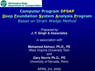
Computer Program DFSAP D eep F oundation S ystem A nalysis P rogram Based on Strain Wedge Method. Prepared by J. P. Singh & Associates in association with Mohamed Ashour, Ph.D., PE West Virginia University Tech and Gary Norris Ph.D., PE University of Nevada, Reno APRIL 3/4, 2006.

E N D
Computer Program DFSAPDeep Foundation System Analysis ProgramBased on Strain Wedge Method • Prepared by • J. P. Singh & Associates • in association with • Mohamed Ashour, Ph.D., PE • West Virginia University Tech • and • Gary Norris Ph.D., PE • University of Nevada, Reno • APRIL 3/4, 2006
WORK PROGRESS • PHASE I • S-SHAFT PROGRAM FOR SHORT SHAFTS • ONE-ROW SHAFT GROUP (AVE. SHAFT) • SHAFT CAP (for one row of shafts) • SOIL LIQUEFACTION • PHASE II • INTERMEDIATE / LONG PILE/SHAFT • SHAFT/PILE GROUP • ISOLATED SHAFT AND SHAFT GROUP • IN LIQUEFIABLE SOIL • LATERAL SOIL SPREAD • PILES/SHAFTS IN SLOPING GROUND • ROTATION & DISPLACEMENT FOUNDATION STIFFNESSES (K11, K22,.......)
PRESENTATION PROGRAM • Comparison between Current Practice and the Strain Wedge Model Technique Used in Program DFSAP • Soil Liquefaction and Anticipated Lateral Spread, and their Effect on Pile/Shaft Response • Short/Intermediate/Long Pile/Shaft in Liquefied & Nonliquefied Soil Profiles, and Pile Cap Effect • Axially Loaded Piles and Piles in Sloping Ground • Linear and Nonlinear Equivalent Stiffness Matrix for Bridge Foundations • DFSAP Program Demonstration (Input and Output Data)
Y Z X X Z Column Nodes K11 Foundation Springs in the Longitudinal Direction K22 K66 Y Transverse Longitudinal
Pv Mo p Po ( E ) s 1 y p ( E ) s 2 y p ( E ) s 3 y p ( E ) s 4 y p ( E ) s 5 y Laterally Loaded Pile as a Beam on Elastic Foundation (BEF)
DIFFERENCES BETWEEN THE TRADITIONAL P-Y CURVE AND PROGRAM DFSAP • Traditional p-y Curve Does Not Account for the Following: • Pile Bending Stiffness (EI) • Pile Head Conditions (Free/Fixed) • Pile Cross-Section Shape (Square/Circular/H-Shape) • Pile-Head Embedment Below Ground • Soil Profile Continuity (Winkler Springs) • It was developed for Long Piles • Empirical Parameters • Soil Liquefaction and Lateral Soil Spread • Pile Group • Vertical Side Shear Resistances • (Large Diameter Shaft)
P P 4 ft 4 ft K1 K2 Effect of Structure Cross-Sectional Shape on Soil Reaction Laterally Loaded Pile as a Beam on Elastic Foundation (BEF)
As presented by Terzaghi (1955) and Vesic (1961) L C B Footing q per unit area H Rigid Footing, Kr = 0.5q Flexible Footing, Kr = 0 Kr = q Kr = 0 (1-2s) EP H3 Kr = 6 (1-2P) Es B3 Effect of the Footing Flexural Rigidity (EI) on the Distribution of the Soil Reaction
EI 0.1 EI The traditional p-y curve (in LPILE) does not account for the pile/shaft EI variation Based on the Strain Wedge Model Analysis
Pv Mo Pv Po Mo y o Po T o FP Fv z FP Fv S o i l - S h a f t S h e a r R e s i s t a n c e FP Fv p v y S o i l - S h a f t H o r i z o n t a l R e s i s t a n c e Mt Ft Vt N e g l e c t e d w i t h L o n g S h a f t s T T i p R e a c t i o n D u e t o S h a f t R o t a t i o n LARGE DIAMETER SHAFT
Ashour and Norris UNR SAND CLAY C- ROCK The Basic Strain Wedge Model in Uniform Soil
F1 Real stressed zone C h * CD* dx = * CD * ds sin m m Mobilized zones as assessed experimentally h A A m Pile head load Po m Pile p Pile No shear stress because these are principle stresses m Side shear () that influences the oval shape of the stressed zone Successive mobilized wedges m B F1 Plane taken to simplify analysis (i.e. F1’s cancel) (b) Force equilibrium in a slice of the wedge at depth x Yo VO Sublayer 1 ds x i-1 KVO h dx h Hi i Sublayer i+1 m (c) Forces at the face of the soil passive wedge (Section elevation A-A) Fig. 5 Relationship between the real Mobilized stress zones and the SW model passive wedges
Stress Yield Stress (f ) y c f cc E E E E c s s s E so f s Compressive stress, f E cc Strain g g y cc g g cu g Compressive Strain, Uniaxial Elastic-Perfectly Plastic Numerical Steel Model s c Pile/Shaft Nonlinear Material Modeling Stress-Strain Model for Confined Concrete in Compression
Validation Example (Chapter 6)
2-ft-Diameter Free-Head Shaft Response at the UCLA Test Shaft Length = 25 ft (Bridge Conference, Oct. 2005)
Pv Po Single pile psingle p Pile in a group pgroup = fm psingle y P-multiplier (fm) concept for pile group (Brown et al. 1988) PILE GROUP
PILE GROUP Configuration of the Mobilized Passive Wedges, and Associated Pile Group Interference
(Po)g (Po)g Uniform pile face movement Pile Pile Overlap of stresses based on elastic theory (and nonuniform shaped deflection at pile face) Overlap employed in SW model based on uniform stress and pile face deflection Horizontal passive wedge interference in pile group response
Validation Examples (Report, Chapter 6) • Lateral response of pile-group (P vs. Yo) • Response of individual piles in a group • p-y curves of individual piles
Validation Example (Report, Chapter 6) • Limitations of traditional p-y curves • Lateral response of isolated shaft • and shaft-group • Vertical shear side resistance effect on • diameter shafts
Shaft B1 Shaft B2 The Taiwan Test by Brown et al. 2001
In order to match the measured data using LPILE, the traditional p-y curves were modified as shown above (Brown et al. 2001)
4000 M e a s u r e d ( B r o w n e t a l . 2 0 0 1 ) N P r e d i c t e d ( S W M o d e l ) k N o V . S i d e S h e a r , W i t h V . S i d e S h e a r 3000 o P , d a o 2000 L d a e H F r e e - h e a d 1000 e l i P 0 0 40 80 120 160 200 P i l e H e a d D e f l e c t i o n , Y , m m o S i n g l e 1 . 5 - m - D i a m e t e r Shaft (B1)
Validation Example (Treasure Island Test) • Validation of pile classification in DFSAP • Response of individual piles in a group
Treasure Island 3 x 3 Pile Group Test (Rollins et al., ASCE J., No. 1, 2005)
Validation Example Report, Chapter 5 • 3 x 3 Pile group in soil Profile-S5 from WSDOT • Design Manual • Pile Cap Contribution • Pile-head effect (free and fixed)
3 x 3 SHAFT GROUP OF 2-FT LENGTH IN SOIL PROFILE S-7 FREE-HEAD, EXAMPLE 2
3 x 3 SHAFT GROUP OF 2-FT LENGTH IN SOIL PROFILE S-7 FIXED-HEAD, EXAMPLE 2
FREE-HEAD FIXED-HEAD