Download
1 / 19
190 likes | 364 Views
LHC Collimation Project Integration into the control system . Michel Jonker External Review of the LHC Collimation Project 1 July 2004. LHC Collimation system. Up to 120 collimators including tertiary, scrapers, absorbers, phase 2, etc

E N D
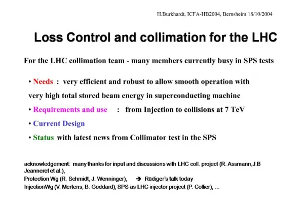
LHC Collimation ProjectIntegration into the control system Michel Jonker External Review of the LHC Collimation Project 1 July 2004
LHC Collimation system • Up to 120 collimatorsincluding tertiary, scrapers, absorbers, phase 2, etc • Distributed over 6 points with a large concentration in point 3 and 7 • Jaw positions are correlatedprimary – secondary – tertiary • Also during movements!they have to stay in sync
Collimator control A single collimator has • 5 stepper motors • 5 resolvers (position measurements coupled to the motor axes) • Other position measurements • Potentiometers • LVDT’s • Operational condition sensors • Temperature gauges • Water pressure • Water flow • Accelerometers • Audio recorder
Local position control Local Collimator Control • Position Control • Stepper motor control • Position readout and survey • Readout of other parameters • May include the redundant position measurements. • Generation of beam dump signal Under study: • PLC or • Integrated electronic system • PLC
Position Control Systemsubject of a market survey A position control system assembly • controls multiple motors (up to 100 per assembly) • may be either: • A PLC based system Responsibility for the development of PLC software should be part of the market survey. • An integrated electronic control system (e.g. like in LEP) In either case we need: • a communication interface with the system based on the modbus protocol (or equivalent). I.e the assembly looks like a PLC. • to have the right and the support to modify embedded software. (I.e. have the possibility to in-source the maintenance.) The real issues here are: • Low electric noise in motor control (no chopper supplies) • Control over long distances
Local position control Local position control Collimator Control Architecture Feedback Application Control Applications Beam Loss Signals Setting Database Central Collimator Control Beam dump Timing distribution Modbus on Ethernet .....
Modes of operation Based on various operational scenarios Used to define functional requirements • Without beam present • Unsynchronized movements • With beam present • Synchronized & position-surveyed movements • Unsynchronized fine adjustments of individual collimator jaws
Modes of operation Unsynchronized movements • When No beam present • Position calibration procedures • Prepare for injection • No global synchronisation required. • Both sides of a jaw have to remain within 1 mm • Is the responsibility of local position control Mechanical speed limit: < 10 mm/s • Time to detect problems 100 ms (is acceptable)
Modes of operation Synchronized position-surveyed movements • When Beam present • Movements during the ramp or during the squeeze • Global synchronisation required (movements start at the same time) • Detection of positioning errors during movements. • Maximum tolerable error may vary (can be as small as 25 m) • Drive speed limit = max error / system response time E.g. 25 m / 100 ms = 0.25 mm/s In case this is in the resonance range of the assembly, the speed should be further reduced. (Continuous single step mode).
Modes of operation Unsynchronized fine adjustments(individual jaws) • Under control of the operator • Driven by feedback from beam-loss systems • When Beam present • At injection, the end of the ramp, or in preparation of physics • No global synchronisation required (mostly one or two motors per command) • Commands to move by a few (1 – 5) steps at the time • Command rate up to 10 Hz (feedback driven) • Speed: a few times 50 m/s
Functional Requirements Motor Control • Controlled by preloaded movement functions: • Movement functions are triggered by a common hardware or software signal (common to the assembly). • Movement functions can be simple or complex. • Simple functions are used for tweaking collimator positions. • Complex functions for calibration, ramp
Functional Requirements • Examples of movement functions • Simple function • start condition, • time, displacement • stop condition • Displacements are either absolute or relative • Complex function • start condition, • n x { time, displacement} • Stop, pause, conditions • Displacements are either absolute or relative
Functional Requirements Motor Control(cont.) • Movements are interruptible by external stop signals (hardware and/or software) • Actual motor position can be re-initialized. • External hardware conditions are recorded by the system and are reported to the supervisory system. • The theoretical positions can be read at any time by the supervisory system. • The system maintains a history in terms of executed motor steps. The history is kept in non volatile memory. (Post mortem analysis)
Functional Requirements Resolver Readout • Autonomous readout and position error detection by the system: • The system continuously measures and compares, independent of a supervisory system. • Position errors are signalled by HW output signals and by software reports to the supervisory system. (different error thresholds?) • Acquisition and position error detection is also active during movement: • Needs to receive functions that specify position and tolerance. • Needs to receive time synchronisation signals (to follow motor control functions)
Functional Requirements • Error thresholds vary during movement (they are more strict when closer to the beam) • Error thresholds can be asymmetric • Can be represented by a minimum and a maximum bound function. • Use similar function format as for motor control
Functional Requirements Resolver Readout (cont.) • sampling speed (adjustable?) • @ 50 ms: 14 bits = precision 2.5 um (40 mm /16384) • @ 10 ms: 13 bits = precision 5 um (40 mm / 8192) • The resolver readout system uses same hardware start and stop signals as the motor control. • The actual positions can be read at any time by the supervisory system. • A history is kept in non-volatile memory for post mortem analysis.
Feedback Application Control Applications Beam Loss Signals Setting Database Central Collimator Control Beam dump Timing distribution Modbus on Ethernet ..... Local position control Local position control Central Collimator Control • Provides a ‘standard equipment’ view to the LHC control system. • Accepts command for ramp • Accepts actual setting trims. • Coordinates the movements between the individual collimator assemblies. • Reports changes to the application layer for logging. • Listens for error reports and acts on them. • Acts as a gateway to relay FB information from the Beam Loss systems to the local position control systems. • Implemented on a VME system running LynxOs Central Collimator Control
Conclusions: Local Collimator Control Readout of collimator operational conditions does not pose any problem (PLC based). Details of the local architecture still uncertain due to the uncertainty of the local motor control system. • There is one potential candidate that may provide an integrated electronic assembly. (Based on the electronics for the Lep System) • There are possibly many PLC based solutions but which needs to demonstrate their capability to comply with the low electric noise requirements. • Essential points • Low electric noise, long distances • Function driven motor control • Position Acquisition: precise, fast, autonomous, including position error detection capabilities • Post mortem history buffers.
Conclusions: Central Collimator Control • Functionally very similar to other LHC equipment. • Based on common LHC control architecture. Phased implementation ? • Simple setting control for day 1 • Use of functions and position survey during movements • Feedback based on beam loss signals However, all these modes of operation have to be foreseen in the control system right from the beginning.