
Chapter 10
Dimensioning and Tolerancing. Chapter 10. Dimensioning Components. Dimension lines-determine the extent and direction of dimensions Extension lines indicate the point on the object that the dimension applies to. You will need to be able to label these parts as on a test. .200, 5mm .

Chapter 10
E N D
Presentation Transcript
Dimensioning and Tolerancing Chapter 10
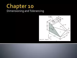
Dimensioning Components • Dimension lines-determine the extent and direction of dimensions • Extension lines indicate the point on the object that the dimension applies to. You will need to be able to label these parts as on a test
.200, 5mm .0625, 1.5mm . 25, 6mm .125, 3mm .0625, 1.5mm .0625, 1.5mm
Mechanical drafting standards Text height • .10 or .125 inches • 3 mm Arrow Length • .125 inches • 3 mm Arrow style Filled Non-filled
Leaders • Used to direct dimensions, notes, symbols, item numbers or part numbers to features on a drawing. • Typically drawn at 30˚, 45˚or 60˚ • Never drawn horizontal or vertical
Uses for dimensions • To make the part • To design mating parts • To design tooling that will be used to manufacture the part • To check inspect parts that have been manufactured to make sure they are correct • To design Jigs and fixtures to aid in production and assembly
Working Drawings A drawing from which a part can be produced, a complete set of instructions. Working Drawings consist of: • Views necessary to explain the shape of a part • Dimensions needed to create the part • Specifications (material, manufacturing process, etc.)
Good dimensioning practices Drawings need to be neat and easy to understand!! • Keep about .5” distance from the part to the first set of dimensions • Keep about .3” between rows of dimensions • Always use single style of arrowhead and font throughout the entire drawing • Do not dimension hidden lines • Try to keep dimensions off of the object when possible
Tolerances Tolerances are permissible variations in the specified form, size or location of a feature of a part. • Parts cannot be manufactured exactly • Allowances for minor variations must be given in order to be able to efficiently manufacture parts
Types of tolerances Bilateral Tolerance-allows the specified dimension to vary in two directions. Unilateral Tolerance-allows the specified dimension to vary in only one direction.
Limits Limits are the largest and smallest size a part can measure when referencing a tolerance. Limits of this toleranced dimension: 1.502 1.498
Reference Dimensions Used for information purposes only Can be: • A dimension that has already been specified by other dimensions • Repeat of a dimension already given in another view • Used to clarify what’s intended but not used to manufacture or inspect
Shown by dimension in parenthesis - (85.5) Or with REF after the dimension - 85.5 REF Without reference dims With reference dims
Reference Dimensions used in section view to identify objects already dimensioned
Dimensioning Units International System of Units (SI Metric) • Uses millimeters (mm) • Whole numbers: 10, 10.5 • No trailing zeros: 10.50 • Should have the same number of decimal places on the dimension and the tolerance • 1.000±.010 NOT 1.000±.01 Decimal Inches • U.S. Customary method • Number of decimal places used to determine accuracy of tolerances: 1.5, 1.50, 1.500 • Usually 2 or 3 decimal places • Zero before decimal if value is less than 1 • 0.8
Fractional Units • Not commonly used on engineering drawings • Require large tolerances • Can be used to call out a feature that is made by a tool measured in fractions (drill bits) • Used to call out a dimension of little importance
Angular Units Decimal Degree (preferred) • 10˚ • 10.5˚ • .5˚ • Degrees, Minutes and Seconds • 10˚30’ • 0˚45’ • 10˚30’45”
Dual Dimensioning Dimensioning using two units of measurement (inches and mm) • For drawings that will be used by companies that use different units • Format being used must be identified in a note 0n the drawing
Format for Dual Dimensioning Inches [mm] Inches [mm] *Can be mm first


