Download

1 / 24
240 likes | 418 Views
Guardian & Vortex Shedder Sealing System Presentation. Advanced Sealing Technology For Steam Path Efficiency Improvement Above OEM Design. Bucket Tip Leakage. Steam Deflectors (Spill Strips). Stationary Diaphragm. Design Steam Path. Stationary Blade. Rotating Blade. Packing Ring.

E N D
Guardian & Vortex Shedder Sealing System Presentation
Advanced Sealing Technology For Steam Path Efficiency Improvement Above OEM Design
Bucket Tip Leakage Steam Deflectors (Spill Strips) Stationary Diaphragm Design Steam Path Stationary Blade Rotating Blade Packing Ring Rotor Wheel Packing Leakage Turbine Rotor Typical Impulse Steam Path (i.e. GE, Hitachi, Toshiba, etc.)
Conventional Spill Strip Reduced Bucket Tip Leakage form the Vortex Shedder Vortex Shedder Shape Applied to the Spill Strip only on the 1st up stream tooth Stationary Diaphragm Design Steam Path Stationary Blade Rotating Blade Guardian Packing Ring Rotor Wheel Reduced Packing Leakage Turbine Rotor Typical Impulse Steam PathWith TPL’s Advanced Seals
Typical Reaction Steam Path (i.e. Westinghouse, ABB, Mitsubishi, Kraftwork Union) uses inserted Seal Strips Stationary Cylinder Steam Flow Rotor
Typical Efficiency Losses per Stage for General Electric Turbines
What Can Cause Rub’s • Misalignment, Alignment is Critical for all current seal Designs • Balancing • Thermal Distortion • Harmonics • Bearing Oil Whip • Steam Whirl • Generator Transients • Incorrect Operation of the Boiler, Condenser, Generator, or Extractions • Improper Starting and Loading Procedures for the Turbine Generator
What Occurs During RubsFor Other then Guardian Designed Seals • Practical Application Concerns • If a rub does occur there is a permanent loss of seal efficiency • Springs do afford very little give or release if a rub conditions does happen • Conventional tooth material has a relative high coefficient of friction. • A rub can result in a hot spot which could lead to rotor bluing, scoring, or cutting. Worst case a bowed rotor. • Hard and prolonged contact of the seal in a rub can result in a heat effected zone on the rotor increasing the possibility of a hydrogen embrittled area. • Conventional tooth material mushrooms increasing the discharge area of the seal. This adds to a greater efficiency loss
Guardian Seals • Theory Behind Design • Prevents damage to conventional seal in any rub situation • No stationary fit modifications required • Works in any OEM designed turbine • Will not cause bowed rotors • Works in any Labyrinth Seal Ring • Location or Application • Works in any steam condition • Works in any Pressure condition • Extends Seal Efficiency Life • Extends unit Heat Rate between • Overhauls • Improves unit reliability • Limits seal degradation
Guardian Seals • Practical Application • Lighter coil springs lessen radial forces only during startup • The Guardian Post contacts the rotor first and prevents damage to the conventional teeth • When rubs do occur with the Guardian they do not grow in intensity as with conventional materials or Brush Seals • Conventional teeth still maintain factory radial Clearance during and after the rub occurs • Guardian Post Material with its low coefficient of friction and long wearing characteristics prevents damage to the rotor body even during extreme rub conditions. • Rubs during startup are proven not to cause rotor instability and/or higher bearing vibration • Long term rubs due to misalignment have been proven not to cause any adverse effects in turbine operations. • The Guardian Seal Can Not remain in a Retracted position. Thus eliminates this potential for major efficiency losses due to this situation
Laboratory Hard Rub Test • Standard Tooth • Guardian with Standard Teeth • Note the discoloration cased by hard rubbing which generated intense heat at the tooth tips • Note only light contact because of the Guardian Seal Protection Test Procedure : Rotor Spinning at 3600 RPM, Seal pushed downward against the rotor with 5,000 lbs. of force for 40 minutes
Test Rotor Before Cleaning After Partial Cleaning • Guardian transferred a protective layer of Proprietary Material to the rotor. • Proprietary Material rubbing on Proprietary Material has an extremely low coefficient of friction. • Low coefficient of friction means very little heat generated by contact • No Scoring or Grooving on rotor where the Guardian seal contacted the rotor. • No heat effected zone where the Guardian Seal contacted the rotor. • No change in rotor hardness where the Guardian seal contacted the rotor
BRG # 2 HP-IP Turbine ran without oil, there was ≈ 1/8” of babbit prior to accident. The rotor dropped straight down and ran on the seals
N3 Grv 5 HP-IP • This gland is adjacent to the #2 Bearing in the previous slide
N3 Grv5 N3 Grv6 HP-IP Note Oil Deflector damage to rotor, No damage where the Guardian Posts made contact to rotor, it only polished the rotor. Even the conventional teeth did not cause any damage because of the protection provided by the Guardian Posts
Guardian Post Conventional Teeth N3 Grv 6 HP-IP This is the bottom center segment from N3 Grv 6, Note the minor damage to the Guardian Post and conventional teeth. The packing ended up supporting the weight of the rotor during the accident.
Bottom Segment Bottom center segment view, Note minimal damage to Guardian Post and conventional teeth
N3 Grv 6 HP-IP Opposite end view of the bottom center segment NOTE: Where all conventional packing rings were installed in the unit, the rotor required machining to remove heat effected zones created from the sever rubs at these locations. No rotor machining required where Guardian Rings were installed.
Design Applications • Seals by providing pressure drops using relative tight radial clearances (same principle as a nozzle) • Stationary • Typically Material selection based on Stage operating temperatures • Spring backed NOT Spring loaded. This design allows for ease of installation only.
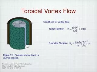
Vortex Shedder Efficiency Improver
Design Applications • Reduces axial flow or leakage in a CFD modeling by 5.7% when compared to a conventional straight shape. • This savings translates into 1.5-2.2% turbine steam path efficiency improvement above design • The reduction in flow is accomplished by creating vortices at the tip of the seal. These vortices act as a pressure barrier thus reducing the pressure drop across the seal. • Lower flow means higher efficiency. • Lower flow also means less wear. • All tip seals are manufactured from a non-sulferized 12Cr material • Uses OEM design Radial Clearances
Typical Reaction Steam Path using inserted Seal Strips Radial Seal Height must be at least 0.200 inches in order to effectively install the Vortex Shedder Stationary Cylinder Only one tooth on the steam admission side gets the Vortex Shedder Steam Flow Rotor