3G-NODE-B MIGRATION TO
Learn about migrating Node-Bs to Ethernet backhaul for higher bandwidth. Discover advantages, challenges, solutions, and network details for a seamless transition.

3G-NODE-B MIGRATION TO
E N D
Presentation Transcript
3G-NODE-BMIGRATION TO ETHERNET BACKHAUL BB UNIT
Introduction • At present , Node-Bs are using TDM backhaul for the connectivity with the RNC. The bandwidth used are nXE1 where n varies from 3 to 12. • In order to provide higher bandwidth to customers, we need to migrate to Ethernet backhaul. • Currently, there are 1126 Node-Bs and 13 RNCs. Out of 1126 Node-Bs, 699 are working on OFC. Agenda
Advantages and challenges Advantages • Ethernet can provide higher bandwidth . • Cheap and better economy of scale. • Efficient transport. Challenges • Lacks simple and reliable synchronization functionality of TDM. Solution • IEEE 1588 PTP –for synchronization Agenda
3G- NETWROK DETAILS BB UNIT
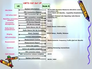
3G-Line Diagram-Data 1+1 GE 4 GE Node-B RNC SGSN GGSN Unchannelised STM-1. To be upgraded to match with the Ethernet backhaul upgradation. FE 100 Mbps NME-1
Interfaces-Node B and RNC • SFPs are required to support FE optical at Node-B end. • There are 13 RNCs with 3 different types. GE port which will be made available by vendor are: • Synchronization requirement will be met M/s Huawei supplied IEEE 1588 server. This will be used to distribute synch signals through Ethernet backhaul. Agenda
RNC-Node-B Details-1 Agenda
RNC-Node-B Details-2 A4: 3 GoU Boards, 6+6 A3: 2 GoU Board, 4+4 A2: 1 GoU Board, 2+2 Agenda
BB- NETWROK DETAILS BB UNIT
BB AGGREGATION NETWORK-1 NME-1
BB AGGREGATION NETWORK-2 NME-1
BB AGGREGATION NETWORK-3 NME-1
BB AGGREGATION NETWORK-4 NME-1
INTERFACE DETAILS BB UNIT
Interfaces-3G • FE ELECTRICAL • OR • b) FE OPTICAL SFP NODE-B RNC GE OPTICAL SFP NME-1
Interfaces-Broadband GE: GE-LH-40 UTSTARCOM 1XX0878700-H(as seen in Vellore) RPR Tier 1/Tier2 FE: FE-FX-PHY-UTSTARCOM 1XX0924906-F(as seen in Vellore) Availability of SFPs to be checked OCLAN FE: 155Mbps,2Km,850 nm Rodevices make (as seen in Vellore) GE: 1.25Gbps,30Km,1550nm Rodevices make (as seen in Vellore) *4 ports of GE can be made as Electrical also NME-1
Interfaces-TRANSMISSION WTD RTXM 139-400 WHTD 004201 155m,15Km,1310nm-SM-ESFP(as seen in Vellore) CPE-8 Availability of SFPs to be checked MADM-16 FIBER XON 1310nm 155m SFP(as seen in Vellore) FTTH-ONT NME-1 4 FE electrical
OPTIONS AND CHALLENGES BB UNIT
Various Options and its challenges-1 • Riding over BB Aggregation Ring i.e RPR Ring. RPR are mostly intra city rings. The rings are not available in all SSAs and very few of them are 10G. Already, NME-University(155 Mbbs), GPON/GEPON, WiMaX, IPTAX,IPTV,VPN use this ring for transport. This is apart from the DATAONE Traffic the purpose for which the ring has been designed originally. • Some Tier2 switches do not support FE interfaces. The availability of SFPs are very limited. Agenda
Various Options and challenges-2 • Capitalizing on FTTH services :GPON and GEPON based FTTH services are available at following locations only. Agenda
Various Options and challenges-3 • Using the combination of MADM-16 Rings with CPE-8. SFP availability limited. • Using the combination of FTTH and CPE-8. • Using the combination of Tier2 and CPE-8. SFP availability to be checked. • Using E1-FE converter /WDM splitter. • Using the MADM-16 Rings. Agenda
SCENARIOS POSSIBLE-1 • Using RPR Ring • Node-Bs co-located with RPR Tier1/Tier2. • Node-Bs Nearer to Tier1/Tier2: Drive distance of SFP and availability of fibre pair are critical. If not WDM splitter may be used. • Node-Bs which are built-Up to Nearest Tier1/Tier2 station using CPE-8 sytems : Use 1310 nm SFP at Tier1/Tier2end. • Using FTTH ONU-s which have FE electrical. • Using the combination of FTTH and CPE-8: Use FE electrical interfaces available at both ends. • . • Using the MADM-16 Rings. Agenda
SCENARIOS POSSIBLE-2 • Using the MADM-16 Rings • Node-Bs co-located with MADM-16 terminal: Use FE electrical available at both ends. • Node-Bs which are built-up to the nearest MADM-16 Station by using CPE-8 Systems: Use FE electrical available at both ends. • Using the Aggregation Switch : Built media upto Aggregation switch which should be located at RNC end. • Using E1-FE converter /WDM splitter Agenda
DIRECT CONNECTIVITY USING SFP • If Tier 1 or Tier 2 are located within the drive distance of SFP and spare fibre is available from Node-B location to Tier1/2 location, 1310nm SFP at Node-B end can be used. Please ensure 1310 nm SFP at Tier1/2 end which may be available spare from CPE-8/MADM-16 systems. BB UNIT
CONNECTIVITY USING CPE-8 system • If Tier 1 or Tier 2 location is used as Built-up stations for distant end Node-Bs (using CPE-8 systems), put the 1310nm SFP at Tier 1 or Tier2 and provide connectivity. BB UNIT
USING MADM RING • MADM-16 Ring Nodes can also be used to carry FE traffic from CPE-8/Node-Bs. MADM terminal in the ring which is co-located at RNC end can also be used to aggregate FE to GE. BB UNIT
AGGREGATION SWITCH • Aggregation switch can be deployed at RNC location for aggregating Node-B traffic in FE interfaces and then make it as GE towards RNC. BB UNIT
ISSUES-1 • Node-Bs generate about 3X14.4 ~ 50Mbps traffic. Hence, riding over RPR ring shall be attempted only in 10G ring locations(8) viz CBE,ERD,MA, PY,SLM,TR,TVL and VLR. (CBE no FE I/F) • FTTH is available at the cities of CBE,TUP,VLR,SLM,PY,TR and MA. Node-Bs at CBE may be connected using GPON as there are 35+ OLTs and are of protected configuration. • Though FE/GE ports are available in BB/TX nodes, very few SFPs are available. Those too, are required for upcoming BB expansion project. Agenda
ISSUES-2 • It is not clear whether SFPs will be made available to all Node-Bs. • RNC interfaces, both uplink and downlinks shall suitably be upgraded. To derive the max benefit, all the connectivity in the chain shall be augmented. • Replaced CPE-21 shall be properly reused. ODF/FDF,Patch cords, connectors, SM-MM convertor(modal conditioning patch cords) etc are required depending on the site conditions. Agenda
ISSUES-3 • Synchronizations to be ensured; otherwise call will drop.(No handover with adjacent cell possible ) • RNCs located at CBE,TNJ,TT,TVL and PY serve adjacent SSA also. In that scenario, separate 1+1 GE interface to be allocated at RNC end for connecting the adjacent SSA Node-Bs. • The present traffic of MADM-16 Ring shall be studied before attempting to use it. Agenda
CASE STUDY-PY BB UNIT
RNC-CONNECTIVITY-PY(LOGICAL) 1310,GE,SM,LC 1550,GE,SM,LC RNC TIER 1 ODF In the case of PY SSA, both RNC and Tier 1 are co-located in the same floor. One ODF was also availabe in the MSC SWITCH ROOM which is used for interconnection. 1+1 GE interfaces available in both RNC and Tier1 are used for interconnection. Though wavelength is different, it will work since the receiver in both ends will normally be Wideband but the range will be limited to the lower of the two. NME-1
PY MADM –RPR-RNC-LOGICAL LSP NNR MUP ENR RBN MADM RING 1 MADM RING 2 OKP KET PY MAIN RNC TKM ARK AVE PY PY GE GE FE FE PY MADM RING 5 GE T1 KIU MADM RING 3 PY PY T2 MTP VIN T1 T2 LSP BHR RPR T1/T2 MKM VIN TCM T2 T2 OKP BB UNIT
CO-LOCATED NODE-B(WITH Tier 1 or 2) 850nm,FE/GE,MM,LC Node-B 850nm,FE,MM,LC Tier 1 or 2 MM PATCH CORD BB UNIT
OTHER NODE-Bs • Pl refer to the Ann-1(Excel sheet) BB UNIT
THANKS TRANSMISSION UNIT BSNL-TAMILNADU CIRCLE http://www.bsnl.co.in rbabusrinivas@bsnl.co.in THE END