Download

1 / 45
450 likes | 579 Views
LHCONE Research Data Flows - L2 vs. L3. Internet2 Fall 2011 Member Meeting. Anita Nikolich – anikolich@uchicago.edu Brent O’Keeffe – bokeeffe@uchicago.edu. Agenda. Current LHC model UChicago case study LHCONE Overview Layer 2 at the Core Layer 3 at the Edge

E N D
LHCONE Research Data Flows - L2 vs. L3 Internet2 Fall 2011 Member Meeting Anita Nikolich– anikolich@uchicago.edu Brent O’Keeffe – bokeeffe@uchicago.edu
Agenda Current LHC model UChicago case study LHCONE Overview Layer 2 at the Core Layer 3 at the Edge Load Distribution across multiple paths Technical Solution to Address Design Concerns
LHC Experiments ATLAS - one of two general-purpose detectors at the LHC. It will investigate a wide range of physics, including the search for the Higgs boson, extra dimensions, and particles that could make up dark matter. ATLAS will record sets of measurements on the particles created in collisions - their paths, energies, and their identities. 3000 scientists from 174 institutes in 38 countries. CMS - Same scientific goals as the ATLAS experiment, but it uses different technical solutions. More than 3000 scientists collaborate in CMS, coming from 183 institutes in 38 countries
original Site roles in LHC Computing MONARC Tier 0 - CERN Raw Data, First pass reconstruction & Filter; Distribution Tier 1 - in US, Brookhaven Lab Reprocessing Tier 2 Simulation + physics analysis
LHC Overview • LHC Worldwide Computing Grid • >140 sites • >250 CPU cores • >150 PB disk • Creates 6-7 PB Raw Data per Year • All 4 experiments together; more than 120PB/year of data products that are created and stored world-wide.
LHC Network challenges LHC data stresses the R&E general purpose Internet Data will grow more than linearly in next 2 years Processing & analysis capability at Tier-2s will continue to increase with computing improvements Current ATLAS model now allows Tier-2s to pull data from Tier-1s from other clouds & other Tier 2s to meet production schedules, and transfers outputs back to those Tier-1s. (CMS model allows Tier-2s to pull data from any Tier-1)
Uchicago & Atlas • Midwest Tier2: (one of 5 in US ATLAS) • University of Chicago • Indiana University • U Illinois/NCSA (’12) • 417 worker nodes • 13 storage servers (1470 TB) • 15 head nodes • Capacity: • 36,840 HEP-Spec2006 • 4236 job slots, 2GB/slot
ATLAS Tier1 and 2’s US ATLAS Tier1 and Tier 2s, and transfers between them and to Tier 1's in other clouds.
LHCONE Objective 1 - https://twiki.cern.ch/twiki/bin/view/LHCOPN/T2sConn Build an open and neutral global unified service platform for the LHC community. Provide a collection of access locations that are effectively entry points into a network that is private to the LHC T1/2/3 sites. Improve transfers between Tier-1s and Tier-2s and make efficient Tier-2 to Tier-2 Data should be able to be pulled from any Tier-1 but, more importantly, also from any Tier-2 – or even, if possible, from several Tier-2s simultaneously Bos-Fisk report1 – “unstructured” T2 traffic will be the norm LHCONE is not intended to replace the LHCOPN but rather to complement it.
LHCONE requirements* *courtesy of Artur Barcyzk & David Foster Bandwidth: 1 Gb (small site) to multiple 10Gb (leadership) Scalability: Bandwidth growth: Minimal = 2x/yr, Nominal & Leadership sites = 2x/2yr Connectivity: Facilitate good connectivity to under-served sites Flexibility: Ability to include or remove sites at any time Organic activity, growing over time according to needs Initial deployment uses predominantly static configuration (shared VLAN & Lightpaths) A Framework for Traffic Engineering in order to “Empower users”
LHCOnE architecture* *courtesy of Artur Barcyzk & David Foster 3 recurring themes: Flat(ter) hierarchy: Any site can use any other site as source of data Dynamic data caching: Analysis sites will pull datasets from other sites “on demand”, including from Tier2s in other regions. Possibly in combination with strategic pre-placement of data sets Remote data access: jobs executing locally, using data cached at a remote site in quasi-real time. Possibly in combination with local caching
LHCONE Physical From Bill Johnson’s 2011/09/26 Update: https://indico.cern.ch/getFile.py/access?contribId=8&resId=4&materialId=slides&confId=149042
Layer 2 at the Core • Layer 2 Domains act as multipoint, fully-meshed core • Domains joined at the edge • Two VLANs for redundancy and pseudo-load balancing • VLAN 2000 configured on GEANT/ACE transatlantic segment • VLAN 3000 configured on US LHCNet transatlantic segment • Intent is to allow sites to use both transatlantic segments, providing resiliency • 2 route servers per VLAN • Each connecting site peers with all 4 route servers • Interim Solution – Architecture Group is still working on final solution
L2 limitations • A single spanning tree may result in sub-optimal routes within the domain • Limited in scaling globally • Potential for broadcast storm affecting entire domain • Mitigated with storm suppression techniques (custom to each vendor’s implementation) • Broadcast traffic limited/eliminated to prevent storms • Multicast restricted • Building dynamic end-to-end circuits entails more burdensome support model
L3 advantages • Path diversity • Ability to spontaneously collaborate without necessarily needing central coordination • Enables traffic engineering by the end site; LHC data is one of many science flows • Scalable – Can be grown beyond the two transatlantic links today
LHCONE Success Metrics Following are factors used to measure the effectiveness of the LHCONE design • Improved throughput and latency • USAtlas Tier2Ds & European Tier 1 & CERN • European Tier 2’s and BNL & Fermi • US Tier 2 – European Tier 3 • Improving Tier 3 connectivity to Tier 2’s
Current LHCONE Status Launched on March 31st Started shared VLAN service including two initial sites: CERN, Caltech Active Open Exchange Points: CERNLight, NetherLight, StarLight(and MANLAN) Four route servers for IP-layer connectivity installed and operational at CERN, GEANT and MANLAN Midwest pilot locations to include University of Chicago and University of Michigan
uChicago connectivity • Dual 10GE Connections to Regional Networks • MREN • CIC OmniPOP • Layer 2 Peer Mapping to • Brookhaven National Labs for Tier 1 • Indiana University for Midwest Tier 2 • Additional peering needed for new Midwest Tier2 member UI-UC • Dual Layer 3 peering to Internet 2 for fallback ATLAS connectivity
Our Design Principles Isolate high bandwidth science flows from the general purpose IP flows Allow LHC traffic to seamlessly move between IP and dynamic circuit infrastructures such as DYNES Allow end site users to manage their part of the end-to-end path in order to optimize traffic. Allow diversity in case of routing failure Expand beyond the 10Gb site limitation today. Boost network capacity utilization by load sharing VPLS, L3VPNs, whatever protocol is best for your network (BGP, OSPF, ISIS) Connectivity at Layer 3, where appropriate and compatible No cost increases for network
Future Architecture • Larger Data Flows • Bandwidth Availability • Campuses Beyond 10Gb / Up to 20Gb possibly? • MREN versus OMNIPOP • UChicago/UIUC Direct Physical Connection • 100Gb Roadmap • Upgrading Ciena DWDM to 100G Capable – Jan. 2012
Investigating Layer 3 • Connect to LHCONE using two paths • VLAN 2000 via MREN / Starlight • VLAN 3000 via CIC OmniPOP • Routed border to LHCONE Network • Implement Performance Routing (PfR) • Utilizing BGP Local Pref and AS Prepending to prefer one path vs. another • Decision may be based on many factors (Latency, jitter, probe data)
Performance Routing Overview • Cisco Proprietary Protocol • Enhances classic routing with additional serviceability parameters • Reachability, Delay, Cost, Jitter, MOS score • Can use interface parameters like load, throughput and monetary cost • Based on/Enhancement to Optimized Edge Routing (OER)
PfR Components • PfR Border Routers • PfR Master Controller • Performance Measuring • Passive Monitoring • Active Monitoring • Combined
Passive MOnitoring • Uses NetFlow to gather statistics • Delay • Packet Loss • Reachability • Throughput
Policy Application • BGP Route advertisements • AS Path Prepend (Preferred) • AS Community • Exit Link Selection • BGP Local Preference (Preferred) • Static Route Injection • Policy Route • Protocol Independent Route Optimization (PIRO)
uCHicago Implementation • Fully utilize dual Regional Network connectivity • Control path utilization based upon shared link performance • Optimize path selection based on NetFlow performance statistics • Provide measurable data to report on success factors
PFR Pros/Cons PROS • Simple / Automated Solution for Traffic Engineering requirement currently missing in LHCONE Architecture • Works with current LHCONE Design • Provides statistics on traffic patterns CONS • Cisco Proprietary • Requires multiple exit paths to LHCONE VLANS • Though can be applied to VLAN sub-interfaces • Short-term solution to address current LHCONE Architecture Limits • May create complex routing advertisements depending on granularity • Cisco Proprietary……..
Proof of Concept Utilize GNS3 to Model the Routing • Simulate LHCONE Core • Simulate Two remote LHCONE Connected Sites • MIT • MSU • Only use two Route Servers
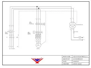
Pre-PFR Flow Without Tuning • Ingress traffic selecting single path (VLAN) • Egress traffic traversing both VLANs via ECMP. • Flows asymmetric • Packets out of order 10.0.0.0/8 is variably subnetted, 4 subnets, 2 masksO E2 10.14.0.0/24 [110/1] via 192.168.16.2, 00:13:57, GigabitEthernet0/0[110/1] via 192.168.16.1, 00:13:54, GigabitEthernet0/0O E2 10.15.0.0/24 [110/1] via 192.168.16.2, 00:13:57, GigabitEthernet0/0[110/1] via 192.168.16.1, 00:13:54, GigabitEthernet0/0 10.0.0.0/24 is subnetted, 3 subnets B 10.14.0.0 [20/0] via 192.16.157.14, 00:18:47 C 10.15.0.0 is directly connected, GigabitEthernet1/0 B 10.16.0.0 [20/0] via 192.16.157.16, 00:19:14
PfR Flow With Tuning • Ingress traffic selecting single path (VLAN) • Egress traffic selecting single path (VLAN). • Symmetric Flow • Packets in order • Automatic redirection in case of congestion 10.0.0.0/24 is subnetted, 3 subnets B 10.14.0.0 [20/0] via 192.16.157.14, 00:18:47 C 10.15.0.0 is directly connected, GigabitEthernet1/0 B 10.16.0.0 [20/0] via 192.16.157.16, 00:19:14 Network Next Hop Metric LocPrf Weight Path *> 10.14.0.0/24 0.0.0.0 0 32768 i * 10.15.0.0/24 192.16.161.15 0 20641 3 i *> 192.16.157.15 0 20641 3 i * 10.16.0.0/24 192.16.157.16 0 20641 160 160 160 160 ? *> 192.16.161.16 0 20641 160 ? Performance Impact 10.0.0.0/8 is variably subnetted, 4 subnets, 2 masksO E2 10.14.0.0/24 [110/1] via 192.168.16.2, 00:13:57, GigabitEthernet0/0O E2 10.15.0.0/24 [110/1] via 192.168.16.2, 00:13:57, GigabitEthernet0/0 Network Next Hop Metric LocPrf Weight Path * i10.14.0.0/24 192.16.161.14 0 100 0 20641 229 i *> 192.16.157.14 150 0 20641 229 i * i10.15.0.0/24 192.16.161.15 0 100 0 20641 3 i *> 192.16.157.15 150 0 20641 3 i
Additional Info Minimum for ISR and 7200 Routers – 12.4(9)T 7600 Series – 12.2(33)SRB Cat6500 Requires IOS 12.2(33)SXH ASR1000 – 3.3.0S Additional PfRNetflow Data Export in IOS XE 3.4Shttp://www.cisco.com/en/US/docs/ios-xml/ios/pfr/configuration/xe-3s/pfr-netflow-v9.pdf FAQ:http://docwiki.cisco.com/wiki/Performance_Routing_FAQs
Alternatives to Cisco Juniper • Real-Time Performance Monitoring (RPM) • Closest Alternative Found • Uses probes to gather performance data • Unable configure routing protocols http://www.juniper.net/us/en/local/pdf/app-notes/3500145-en.pdf INTERNAP • Flow Control Platform (FCP) • Appliance Based • Passively Monitors via Tap • Actively reconfigures routing http://www.internap.com/wp-content/uploads/FCP-Flow-Control-Platform_DS_0511.pdf
Addressing Success Metrics Success Factors • Improved throughput and latency • USAtlas Tier2Ds & European Tier 1 & CERN • European Tier 2’s and BNL & Fermi • US Tier 2 – European Tier 3 • Improving Tier 3 connectivity to Tier 2’s Proposed Solution • Provides ability to actively modify routes to best path (VLAN) based on live statistics – Delay and Throughput • Ensure best path is utilized • Ensure best path is utilized
Review • Science Data Flows are getting Larger • Flows are Becoming Less “Predictable” • Current LHCONE Architecture is short-term • There is a need to address Traffic Engineering • Not easily satisfied at end-sites • PfR solution provides an automated method to address TE need to select the best path (VLAN) • Not only during outage, but during congestion • Provides statistics to help measure LHCONE success factors