Download
1 / 27
730 likes | 1.64k Views
Presentation on Antenna and its parameters. Md Shabbir Hasan Dept. of ECE Institute of Science and Technology. An antenna is a way of converting the guided waves present in a waveguide, feeder cable or transmission line into radiating waves travelling in free space, or vice versa.

E N D
Presentation on Antenna and its parameters Md Shabbir Hasan Dept. of ECE Institute of Science and Technology This is made by Md.Shabbir Hasan ,ECE-827,IST,National University
An antenna is a way of converting the guided waves present in a waveguide, feeder cable or transmission line into radiating waves travelling in free space, or vice versa. This is made by Md.Shabbir Hasan ,ECE-827,IST,National University
Only accelerating charges produce radiation. References This is made by Md.Shabbir Hasan ,ECE-827,IST,National University
Two fields regions: Near field or Fresnel region: The region within the radius of the smallest sphere which completely encloses the antenna is called Fresnel region. In sitting an antenna ,it’s crucial to keep objects out of the near field region to avoid coupling the currents in the antenna with objects. Far Field or Fraunhofer region: The region beyond Fresnel region is called Fraunhofer region This is made by Md.Shabbir Hasan ,ECE-827,IST,National University
Antenna parameters are: 1.Radiation Pattern 2.Directivity 3.Radiation Resistance and Efficiency 4.Power Gain 5.Bandwidth 6.Reciprocity 7.Effective Aperture 8.Beamwidth and Directivity 9.The Friis Formula: Antennas in Free Space 10.Polarisation Matching This is made by Md.Shabbir Hasan ,ECE-827,IST,National University
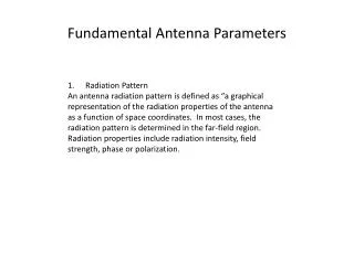
The radiation pattern of an antenna is a plot of the far-field radiation from the antenna. More specifically, it is a plot of the power radiated from an antenna per unit solid angle, or its radiation intensity U [watts per unit solid angle]. This is arrived at by simply multiplying the power density at a given distance by the square of the distance r, where the power density S [watts per square metre] is given by the magnitude of the time-averaged Poynting vector: U=r^²S This is made by Md.Shabbir Hasan ,ECE-827,IST,National University
Antenna parameters are: 1.Radiation Pattern 2.Directivity 3.Radiation Resistance and Efficiency 4.Power Gain 5.Bandwidth 6.Reciprocity 7.Effective Aperture 8.Beamwidth and Directivity 9.The Friis Formula: Antennas in Free Space 10.Polarisation Matching This is made by Md.Shabbir Hasan ,ECE-827,IST,National University
The directivity D of an antenna, a function of direction is defined by the ratio of radiation intensity of antenna in direction to the mean radiation intensity in all directions. This is made by Md.Shabbir Hasan ,ECE-827,IST,National University
Antenna parameters are: 1.Radiation Pattern 2.Directivity 3.Radiation Resistance and Efficiency 4.Power Gain 5.Bandwidth 6.Reciprocity 7.Effective Aperture 8.Beamwidth and Directivity 9.The Friis Formula: Antennas in Free Space 10.Polarisation Matching This is made by Md.Shabbir Hasan ,ECE-827,IST,National University
The resistive part of the antenna impedance is split into two parts, a radiation resistance Rr and a loss resistance Rl. The power dissipated in the radiation resistance is the power actually radiated by the antenna, and the loss resistance is power lost within the antenna itself. This may be due to losses in either the conducting or the dielectric parts of the antenna. Radiation efficiency e of the antenna as e is the ratio of power radiated to the power accepted by antenna antenna with high radiation efficiency therefore has high associated radiation resistance compared with the losses. The antenna is said to be resonant if its input reactance Xa =0. This is made by Md.Shabbir Hasan ,ECE-827,IST,National University
Antenna parameters are: 1.Radiation Pattern 2.Directivity 3.Radiation Resistance and Efficiency 4.Power Gain 5.Bandwidth 6.Reciprocity 7.Effective Aperture 8.Beamwidth and Directivity 9.The Friis Formula: Antennas in Free Space 10.Polarisation Matching This is made by Md.Shabbir Hasan ,ECE-827,IST,National University
The power gain G, or simply the gain, of an antenna is the ratio of its radiation intensity to that of an isotropic antenna radiating the same total power as accepted by the real antenna. When antenna manufacturers specify simply the gain of an antenna they are usually referring to the maximum value of G. This is made by Md.Shabbir Hasan ,ECE-827,IST,National University
Antenna parameters are: 1.Radiation Pattern 2.Directivity 3.Radiation Resistance and Efficiency 4.Power Gain 5.Bandwidth 6.Reciprocity 7.Effective Aperture 8.Beamwidth and Directivity 9.The Friis Formula: Antennas in Free Space 10.Polarisation Matching This is made by Md.Shabbir Hasan ,ECE-827,IST,National University
The bandwidth of an antenna expresses its ability to operate over a wide frequency range. It is often defined as the range over which the power gain is maintained to within 3dB of its maximum value, or the range over which the VSWR is no greater than 2:1, whichever is smaller. The bandwidth is usually given as a percentage of the nominal operating frequency. The radiation pattern of an antenna may change dramatically outside its specified operating bandwidth. This is made by Md.Shabbir Hasan ,ECE-827,IST,National University
Antenna parameters are: 1.Radiation Pattern 2.Directivity 3.Radiation Resistance and Efficiency 4.Power Gain 5.Bandwidth 6.Reciprocity 7.Effective Aperture 8.Beamwidth and Directivity 9.The Friis Formula: Antennas in Free Space 10.Polarisation Matching This is made by Md.Shabbir Hasan ,ECE-827,IST,National University
Reciprocity theorem: If a voltage is applied to the terminals of an antenna A and the current measured at the terminals of another antenna B then an equal current will be obtained at the terminals of antenna A if the same voltage is applied to the terminals of antenna B. This is made by Md.Shabbir Hasan ,ECE-827,IST,National University
Antenna parameters are: 1.Radiation Pattern 2.Directivity 3.Radiation Resistance and Efficiency 4.Power Gain 5.Bandwidth 6.Reciprocity 7.Effective Aperture 8.Beamwidth and Directivity 9.The Friis Formula: Antennas in Free Space 10.Polarisation Matching This is made by Md.Shabbir Hasan ,ECE-827,IST,National University
Effective Aperture If an antenna is used to receive a wave with a power density S [W m2], it will produce a power in its terminating impedance (usually a receiver input impedance) of Pr watts. The constant of proportionality between Pr and S is Ae, the effective aperture of the antenna in square metres: Pr = AeS For some antennas, such as horn or dish antennas, the aperture has an obvious physical interpretation, being almost the same as the physical area of the antenna, but the concept is just as valid for all antennas. The effective aperture may often be very much larger than the physical area, especially in the case of wire antennas. Note, however, that the effective aperture will reduce as the efficiency of an antenna decreases. The antenna gain G is related to the effective aperture as follows G=4pi/ (lamda)2Ae This is made by Md.Shabbir Hasan ,ECE-827,IST,National University
Antenna parameters are: 1.Radiation Pattern 2.Directivity 3.Radiation Resistance and Efficiency 4.Power Gain 5.Bandwidth 6.Reciprocity 7.Effective Aperture 8.Beamwidth and Directivity 9.The Friis Formula: Antennas in Free Space 10.Polarisation Matching This is made by Md.Shabbir Hasan ,ECE-827,IST,National University
The directivity of an antenna increases as its beamwidth is made smaller, as the energy radiated is concentrated into a smaller solid angle This is made by Md.Shabbir Hasan ,ECE-827,IST,National University
Antenna parameters are: 1.Radiation Pattern 2.Directivity 3.Radiation Resistance and Efficiency 4.Power Gain 5.Bandwidth 6.Reciprocity 7.Effective Aperture 8.Beamwidth and Directivity 9.The Friis Formula: Antennas in Free Space 10.Polarisation Matching This is made by Md.Shabbir Hasan ,ECE-827,IST,National University
This is made by Md.Shabbir Hasan ,ECE-827,IST,National University
Antenna parameters are: 1.Radiation Pattern 2.Directivity 3.Radiation Resistance and Efficiency 4.Power Gain 5.Bandwidth 6.Reciprocity 7.Effective Aperture 8.Beamwidth and Directivity 9.The Friis Formula: Antennas in Free Space 10.Polarisation Matching This is made by Md.Shabbir Hasan ,ECE-827,IST,National University
The polarisation mismatch loss is the ratio between the power received by the antenna and the power which would be received by an antenna perfectly matched to the incident wave This is made by Md.Shabbir Hasan ,ECE-827,IST,National University
Antennas and Propagation for Wireless Communication Systems Second Edition Simon R. Saunders and Alejandro Arago´n-Zavala This is made by Md.Shabbir Hasan ,ECE-827,IST,National University
This is made by Md.Shabbir Hasan ,ECE-827,IST,National University
This is made by Md.Shabbir Hasan ,ECE-827,IST,National University