Download
1 / 35
350 likes | 377 Views
Explore the comprehensive IEEE Synchrophasor Measurement Standards, including performance-based strategies, synchronization sources, and technical requirements for improved grid monitoring. Discover the evolution of measurement standards and their impact on grid stability.

E N D
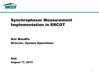
Synchrophasor Measurement Standards Veselin Skendzic Schweitzer Engineering Laboratories Inc.
Synchrophasor Measurement Standards • Over 25 years of continuous improvement • Performance based approach • Interoperability focus
IEEE 1344-1995 • Introduces synchronization sources: GPS, IRIG-B, 1 PPS • Defines synchronizing source requirements: • 0.1 ppm stability • Synchronized within 1s of UTC (0.022° @ 60 Hz) • Max slew rate: 70 ppm (70s/s -> 2 hours for 0.5 s offset) • Describes synchronized data sampling process, but acknowledges other approaches are possible • Requires that PMU input phase delay be compensated by the PMU
IEEE 1344-1995 • Discusses ADC resolution: • 9 bits for voltage, 13 bits for current • Recommends 3 x I nominal full scale • Discusses phasor time tagging • All PMUs must agree in steady state • Provides no transient response requirements • Recognizes window effects but does not specifically enforce the time tag reference (beginning, middle, end) Photo courtesy of Niagara Mohawk a National Grid Company
IEEE 1344-1995 • Time tags: • Identifies 3 possibilities with end of the window being somewhat preferred • Discusses ADC sampling rates • Does not provide clear specification of the reporting rate (transmission rate).
IEEE 1344-1995 Annex C concludes with the statement: Two PMUs of different brands should be expected to yield the same phasor measurement in steady-state. However, two PMUs of different brands (with different algorithms and/or different analog circuitry) can be expected to yield different results for the same phasor measurement in transient state
IEEE C37.118-2005 • Provides formal Synchrophasor definition: • Phasor whose instantaneous phase is reported relative to an ideal cosine function with nominal system frequency; synchronized to UTC. • Clearly defines PMU reporting rates (fixed time grid): • Introduces IEEE 1588 PTP based time synchronization option
IEEE C37.118-2005: Fixed Time Grid Standard states: …reporting times shall be evenly spaced through each second with frame number 0 (numbered 0 through N–1) coincident with the UTC second rollover. • This change recognized phasors are measured over a finite observation window • Time Tag is now effectively in the middle of the observation window (but this is not explicitly stated)
IEEE C37.118-2005 • Frequency step test: • Shows what happens without group delay compensation • Different filters have different group delay (and different length)
IEEE C37.118-2005 • Algorithm agreement after group delay compensation • Center of the window time tag is implied
IEEE C37.118-2005 • Response is non causal, but different filters are able to preserve the exact time of the transient event
IEEE C37.118-2005 • Center timestamp can be compared to the center of gravity of an object • Reference selection is free; but some references make life simpler
IEEE C37.118-2005 • Introduces compliance level concept • Introduces performance based specification concept
IEEE C37.118-2005 • Introduces first set of benchmark tests: • 10% magnitude step test • 90° phase step test • 5 Hz frequency step test • Clear preview of things to come in 2011
IEEE C37.118-2005: Real Life Performance • 2010 BPA test results by Tony Faris • Interoperability is emerging but remains limited • Customer starting to demand custom filters
IEEE C37.118-2005: Real Life Performance • Standard never defined what should happen for the frequency step test • Not surprisingly, nobody was on time…
C37.118.1-2011 • Splits the standard in two parts • Measurements • Communications • Recognizes the need for tighter interoperability requirements • Recognizes the need to support 2 types of applications: • Low latency control applications (P class -> short 2 cycle filter) • Small signal stability analysis (M class -> long filters)
C37.118.1-2011 • Annex C. Introduces PMU Reference Model
C377.118.1 Annex C. Reference Model • Reference model is informative • Alternate implementations are allowed and encouraged • Multiplication with a time synchronized quadrature oscillator introduces modulation artefacts • Frequency tracking PMUs are allowed
C37.118.1-2011 • P class filter: Triangular 2 cycle window
C37.118.1-2011 • M class filter example with frequency response mask:
C37.118.1-2011 Detailed performance requirements: • Steady state phasor measurement requirements • Steady State Frequency and ROCOFF requirements • Dynamic compliance requirements: • Measurement bandwidth • Frequency ramp performance • Step change performance • Response time requirements • Reporting latency requirements
C37.118.1-2011 Steady state requirements example (continued)
C37.118.1-2011 • Detailed compliance test specifications • Several contradicting requirements that over constrained the problem • Standard needed to be amended: C37.118.1a-2014
C37.118.1a-2014 • Well coordinated set of realizable requirements • Takes into account real life PMU performance tests results • Fostered creation of the IEEE ICAP PMU Conformance Assessment and Certification Program
C37.118.1a-2014 Adjustments • Relaxed Table 4. Max RFE requirements for P class • Suspended the M class RFE requirements. • Clarified measurement bandwidth test requirements • Expanded Table 6. recognizing Frequency and ROCOF modulation test performance changes with the reporting rate • Clarified system frequency ramp test and the associated requirements • Adjusted Table 9. and 10. step change performance requirements • Relaxed Table 11. M class PMU reporting latency requirements • Improved Annex C. Reference model filter specification and the frequency mask
PMU Performance Examples • Steady state requirements are easily met but detail behavior may vary depending on the PMU design: M class; 60 FPS PMU A. PMU B. PMU C. Credit: NIST PMU Assessment, Allen Goldstein, NIST 2014
PMU Performance Examples • C37.118-1a provides precise response time limits for the amplitude and phase step tests • M class requires long filters in order to meet the Out Of Band (OOB) interfering signal rejection requirements • M class filters get longer as the reporting rate gets lower • Plots on the right show results for the PMU that passed both OOB and the step response time limit tests Credit: NIST PMU Assessment, Allen Goldstein, NIST 2014
Steady state performance - Frequency tracking PMU example PMU C, Fs = 60 FPS with frequency tracking off. Steady State Frequency from 55 to 65 Hz PMU C, Fs = 60 FPS with frequency tracking on. Steady State Frequency from 55 to 65 Hz Credit: NIST PMU Assessment, Allen Goldstein, NIST 2014
Frequency ramp test - Frequency tracking PMU example PMU C, Fs = 60 FPS with frequency tracking OFF. +1 Hz/s frequency ramp from 55 to 65 Hz PMU C, Fs = 60 FPS with frequency tracking ON. +1 Hz/s frequency ramp from 55 to 65 Hz Credit: NIST PMU Assessment, Allen Goldstein, NIST 2014
IEEE/IEC 60255-118-1: 2018 • Mature standard with future-proof provisions • Digital secondary systems (informative) • Environmental influences (informative) • Performance test subset performed over manufacturer specified temperature range • Extended accuracy (normative) • Use is optional, but certification and specification method is normative • Generator voltage and power angle measurement (informative) • Rotor position measurement • Extended PMU bandwidth classes (normative) • Use is optional, but certification and specification method is normative
IEEE/IEC 60255-118-1-2018 • Extended accuracy concept: • Separate amplitude and phase specifications • Higher accuracy beyond 1% TVE • Wider dynamic range • Improved frequency measurement accuracy