Download
1 / 52
600 likes | 1.04k Views
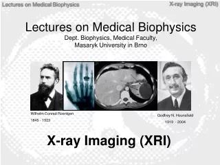
Lectures on Medical Biophysics Dept. Biophysics, Medical Faculty, Masaryk University in Brno. Lectures on Medical Biophysics Dept. Biophysics, Medical Faculty , Masaryk University in Brno. X-ray I maging (XRI). Wilhelm Conrad Roentgen 1845 - 1923. Godfrey N. Hounsfield 1919 - 2004.

E N D
Lectures on Medical BiophysicsDept. Biophysics, Medical Faculty, Masaryk University in Brno
Lectures on Medical BiophysicsDept. Biophysics, Medical Faculty, Masaryk University in Brno X-ray Imaging (XRI) Wilhelm Conrad Roentgen 1845 - 1923 Godfrey N. Hounsfield 1919 - 2004
X-Ray Imaging • X-ray imaging (XRI) is still one of the most important diagnostic methods used in medicine. It provides mainly morphological (anatomical) information - but may also provide some physiological (functional) information. • Its physical basis is the different attenuation of X-rays in different body tissues. • It is important to keep in mind that X-rays may lead to serious health effects (e.g., cancer, cataracts) for both patients and healthcare professionals (HCP). Thus, strict legal radiation protection safety measures exist to avoid any unnecessary harm to both patients and the HCP. We will deal with them in a special lecture.
Content of the Lecture • Projection XRI devices • Image formation and image quality • Projection X-ray devices for special purposes • CT • Radiation dose and health risk
X-Ray Production – Low Power X-Ray Tube used in Dental Units Scheme of an X-ray tube. K – hot filament cathode, W – tungsten plate.
Production of X-rays • An electron with an electric charge e (1.602 x 10⁻¹⁹ C) in an electrostatic field with potential difference (voltage, in this case it is the voltage across the anode and the cathode) U haspotential energy Ep: Ep = U.e • In the moment just before impact of the electron onto the anode, its potential energy Ep is fully transformed into itskinetic energyEK. Thus: Ep = EK = U.e = ½mv2 • On impact, the EKis transformed into x-ray photons (less than 1%) and heat energy (99%). This heat can damage the tube.
Beam Energy and Tube Voltage • If ALL the kinetic energy of the accelerated electron is transformed into a SINGLE X-ray photon, this photon will have energy given by: E = h.f = U.e • This is the maximum energy of the emitted photons. It is directly proportional to the voltage U across the anode and cathode. • Hence if we want to increase the energy of the photons all we have to do is increase the voltage! • The higher the energy of the photons the less they are attenuated by the body - the higher the penetration. This is important when imaging thick body parts or fat patients! ,
Photon Energy Histogram Number of photons with certain amount of energy E
Main Parts of the XRI Device • X-ray tube • Voltage-Current Generator: • High Voltage Transformer– supplies high voltage (up to 150kV) • Rectifier- produces unidirectional tube electron current • When increasing the magnitude of the electron beam current (by changing the cathode heating) the photon fluence rate (i.e. number of photons per unit area per second) of the X-ray beam increases - however the energy of individual photons does not. • The energy of the individual photons can be increased by increasing the voltage between the anode and cathode. • Control panel– today most parameters of the device (including voltage and current) are controlled by means of a computer. It is located outside the examination room or behind a shield made of glass containing lead (to protect the radiological assistant). • Mainmechanical parts: tube stand, examination table, grid for removing scattered photons (‘Bucky’), • X-ray detector: cassette with radiographic film and adjacent fluorescent screens (in radiography) or image intensifier (both on the way out) or flat panel digital detector (in fluoroscopy).
Passage of X-rays through Patient's Body • X-rays emitted from a smallfocal areaof the anode propagate in all directions. In the tube envelope, some low energy photons are absorbed. Further absorption of these photons occurs in theprimary filter, made of aluminium sheet. It absorbs low energy photons which would be absorbed by surface tissues and do not contribute to the image formation (unnecessary patient dose). X-ray beam is delimited byrectangular collimator platesmade of lead. • The rays then pass through the body where transmission or absorption orscattering may occur. After that they pass through thegrid, which is in front of the detector to remove scattered photons as these would degrade the image.
Image Formation and Quality • X-ray image is an analogy of a ‘shadow’ cast by a semitransparent and structured body illuminated by light beam coming form an almost point source. The image is formed due to different attenuation of the beam by the different body tissues and by projection of the structures on a film or an electronic X-ray detector. • The image can be visualised by means of • Radiographic film / screen and subsequent development • Digital plate and displaying image on a PC monitor • Image intensifier and digital CCD camera connected to a monitor in the case of fluoroscopy
Attenuation of Radiation A beam of X-rays (any radiation) passes through a substance: absorption + scattering = attenuation A small decrease of radiation intensity -dI in a thin substance layer is proportional to its thickness dx, intensity I of radiation falling on the layer, and a specific constant m: -dI = I.dx.m After rewriting: dI/I = -dx.m After integration: I = I0.e-m.x I is intensity of radiation passed through the layer of thickness x, I0 is the intensity of incoming radiation, m islinear coefficient of attenuation[m-1] depending on kind of radiation, medium and its density. The mass attenuation coefficientm/r does not depend on the density.
Cassettes for Radiographic Films FLUORESCENT screens reduce dose of radiation about 50-times
Digital Imaging Plates Imaging plate consists of an array of very small sensors digital „bucky“ Matrix of amorphous silicon (aSi) photodiode light sensors phosphor CsI (necessary for patient dose reduction as aSi is not good absorber of X-rays) electronic signal
Image Intensifier R – X-ray tube, P - patient, O1 – primary picture on a fluorescent screen, G – glass carrier, F – fluorescent screen, FK - photocathode, FE – focussing electrodes (electron optics), A - anode, O2 – secondary image on the anodic screen, V – video-camera. Individual parts are not proportionally depicted.
Different Ways how to Obtain DIGITAL Images (mammographic systems) http://www.moffitt.org/moffittapps/ccj/v5n1/department7.html
Blurring of the Image No radiograph (an X-ray image) is absolutely sharp. Boundaries between tissues are depicted as a gradual change of gray scale. This non-sharpness (blurring) has several reasons: • Movement blur– accidental, breathing, pulse waves, heart action etc. They can be reduced by shorter exposure times with more intense X-ray radiation. • Geometric bluris caused by finite focal area (focus is not a point). The rays fall on the boundary of differently absorbing media under different angles – blurring of their contours appears • The light emitted by fluorescent screens attached to the film or digital detector does not only illuminate the corresponding part of the film or detector, but also spreads out to surrounding areas.
Geometric Blur (‘penumbra’) • Geometric penumbra can be reduced by: • Choosing a small focal spot size (but it increases risk of damage to tube anode by heating) • Decreasing the distance between the patient and the detector • - Increasing the distance between the X-ray tube and the patient
Interactions of X-ray Photons with Matter: ABSORPTION by Photoelectric Effect (PE) • Photon disappears (‘is absorbed’) after hitting an atom and an electron is ejected from electron shell of the atom (typically K-shell). Part of the photon energy h.f is necessary for ionisation. Remaining part of the photon energy changes intokinetic energy(1/2m.v2) of the ejected electron. The electron knocks electrons out of atoms of the body and produces ionization of these atoms. TheEinstein equation for photoelectric effectholds: h.f = Eb + 1/2m.v2, Eb is binding (ionisation) energy of the electron. • The probability for PE increases with proton number and decreases with increasing photon energy (this explains why lead is used for shielding and why higher energy beams are more penetrating)
Photoelectric Effect Secondary electron Primary photon
Interactions of X-ray Photons with Matter: Compton Scatter (CS) • At higher energies of photons, the photon energy is not fully absorbed –a photon of lower energy appears. The binding energy of the electron Eb is negligible in comparison with the photon energy. We can write: h.f1 = (Eb) + h.f2 + 1/2m.v2, • where f1 is frequency of incident photon and f2 is frequency of the scattered photon. • CS is more probable than PE for primary photon energies 0.5 - 5 MeV which explains why images at such energies would be practically useless.
Compton Scattering Secondary electron Primary photon Secondary photon
Principle of the Bucky Grid The Bucky grid stops a substantial part of the scattered rays whilst allowing the useful photons to pass through. However unfortunately grids also absorb part of the useful radiation. Hence a higher amount of x-rays must be used to produce a good image – this increases the dose of radiation to the patient. Hence for example grids are not used with thin children as the level of scatter is low anyway. http://www.cwm.co.kr/pro213.htm
Use of the Contrast Agents • The soft tissues only slightly differ in their attenuation. Therefore they cannot be distinguished in a common radiograph. That is the reason for the use of pharmaceuticals calledcontrast agents. • The attenuation of certain tissues can be increased or lowered.Positive contrastis achieved by substances having a high proton number as the probability of the photoelectric effect is increased. A suspension of barium sulphate, “barium meal”, is used for imaging and functional examination of GIT. In examinations of blood, biliary and urinary vessels etc. compounds with high content of iodine are used. • Hollow inner body organs can be visualised bynegative contrast. Air or better CO2 can be used. The cavities are filled by gas, inflated, so that they can be visualised as structures of very low attenuation (pleural space, peritoneum, brain chambers).
Positive and Negative Contrast Horseshoe kidney – positive contrast http://www.uhrad.com/ctarc/ct215a2.jpg Contrast image of the appendix – diverticulosis – combination with negative contrast http://www.uhrad.com/ctarc/ct199b2.jpg Pneumoencephalograph – negative contrast http://anatomy.ym.edu.tw/Nevac/class/neuroanatomy/slide/k42.jpg
Devices for Special Uses • Dental X-ray devices • Mammographic devices • Angiography (image subtraction systems, formerly image intensifier based; now increasingly digital detector based)
X-ray Devices in Dentistry http://www.gendexxray.com/765dc.htm Panoramic screening - orthopantomograpy http://www.gendexxray.com/orthoralix-9000.htm X-ray image of a dental implant
Mammography Mammography is the process of using low-dose X-rays (usually around 0.7 mSv) to examine the female breast. It is used to look for different types of tumours and cysts. In some countries routine (annual to five-yearly) mammography of older women is encouraged as a screening method to diagnose early breast cancer. It is normal to use low frequency X-rays (molybdenum anode).
Digital Subtraction Angiography http://zoot.radiology.wisc.edu/~block/Med_Gallery/ia_dsa.html
Computerised Tomography - CT • The first patient was examined by this method in London, 1971. • The apparatus was invented by English physicist Hounsfield, (together with American Cormack, Nobel award for medicine, 1979)
Principle of CT • Principle: The CT scanner is a complex instrument for measuring the X-rays attenuation in individual voxels (volume analogies of pixels) in narrow slices of tissues. • Method of measurement: A narrow fan-beam of X-rays is passed through the body and the merging radiation measured by an arc of detectors. This is repeated at different angles till enough information is available to be able to calculate the attenuation coefficient in the patient voxels. A „map“ of attenuation is calculated – a tomogram.
Examples of CT Scans Extensive subcapsular haematoma of spleen in patient after car accident http://www.mc.vanderbilt.edu/vumcdept/emergency/apr7xr1a.html Metastatic lesions in brain http://www.mc.vanderbilt.edu/vumcdept/emergency/mayxr3.html
Advantages of CT over Projection XRI • Much higher contrast than projection XRI - 0.5% difference in attenuation can be resolved because: • Almost total elimination of effects of scatter • X-ray measurements are taken from many angles • Thus, we can see and examine different soft tissues. • No overlapping of anatomical structures • Less distortion as measurements are taken from many angles
Four Generations of CT 1. Generation 2. Generation 3. Generation 4. Generation
Principle of Spiral (3D) CT X-ray tube and detectors revolve around the shifting patient
Hounsfield (CT) Units In order to simplify calculations we use Hounsfield Scale units (HU) for amount of attenuation. On this simplified scale water is 0 HU, air is -1000 HU, compact bone is about +1000 HU. A scale of 2000 HU is available for CT examination of body tissues. In most cases, it is senseless to attribute them to all of the grey scale levels (our eye is able to distinguish only about 250 levels of grey). Most of the soft tissue HU values range from 0 to +100. Thus we use only limited „diagnostic window“ of these units in practice, e.g. from -100 to +100. W – water T – tissue k = 1000 HU =
„Diagnostic Window“ of HU <> http://www.teaching-biomed.man.ac.uk/student_projects/2000/mmmr7gjw/technique8.htm
3D Animation http://www.dal.qut.edu.au/3dmovie.html
Some Typical Doses • From natural sources: 2mSv per year • Chest X-ray: <1mSv • Fluoroscopy: 5mSv • CT Scan: 10mSv • Medical doses are increasing with ‘better be safe than sorry’ medicine and the ease of use of modern imaging devices (e.g., spiral CT compared to conventional CT).
Direct Digital Dental Radiography Sensor consists of photodiode matrix covered with a scintillator layer. Wireless sensors now available (using bluetooth or wifi).
Radiation Protection Considerations • Low individual dose but high collective dose technique, particularly since many young patients • Protect eye and thyroid (sometimes latter close to or exposed to direct beam) • As the dose, and therefore the risk to the developing fetus is so low there is no contraindication to radiography of women who are or may be pregnant providing that it is clinically justified. Very Good reference is: • RP136 European guidelines on radiation protection in dental radiology - The safe use of radiographs in dental practice. 2004. EU publication.
Dose Optimisation for Intraoral • Devices • Film speed E or higher • Constant power (CP) generator • filter: 1.5mm Al up to 70kV to reduce skin dose • Rectangular collimator recommended (if round-end collimator used, beam diameter <60mm at patient end of cone) • Digital lower dose than film • Protocol • use 60kV with CP generator • minimum SSD 200mm (cone should ensure this) • There is no need to use a lead protective apron (to protect gonads, except in rare cases) even in cases of pregnant patients. However in the case of pregnant patients, the use of a lead apron continues to be used in some states as it may reassure the patient • Some have suggested using thyroid collar for young patients (in CZ they use it even for adults)
Converting Round Collimators to Rectangular The UK’s Ionising Radiation (Medical Exposure) Regulations 2000 recommend the use of rectangular collimation to limit the radiation dose a patient receives during routine dental X-rays. DENTSPLY’s Rinn Universal Collimator just clips onto any round-headed long-cone X-ray unit, converting it from round to the recommended rectangular collimation, in one easy step.