Download
1 / 22
240 likes | 677 Views
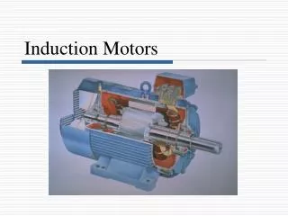
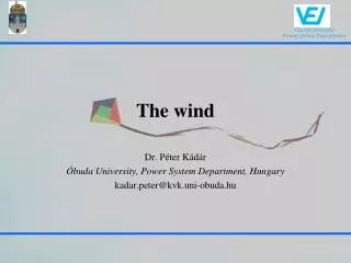
Grid Connection of Doubly Fed Induction Generator Wind Turbines: a survey. Iñigo Martínez de Alegría Mancisidor Jtpmamai@bi.ehu.es. The increasing penetration of wind power in the grid requires wind farms to operate as conventional plants: Past: Present:

E N D
Grid Connection of Doubly Fed Induction Generator Wind Turbines: asurvey Iñigo Martínez de Alegría Mancisidor Jtpmamai@bi.ehu.es
The increasing penetration of wind power in the grid requires wind farms to operate as conventional plants: Past: Present: • Simple energy source Active power control • VAR consumer Active VAR regulation • Fault disconnection Remain connected under fault conditions (fault ride through) -Local wind farm control Remote wind farm control
Simplified grid model X >> R
Voltage/Reactive Power Control In order to participate in voltage control, the wind farm must deliver or sink reactive power in a controlled manner, According to the voltage at the point of common coupling E.On 0.95 inductive, 0.925 Capacitive
-DFIG may control stator reactive power, and grid connected converter may operate as static reactive power compensator (STATCOM) -Only by modifying control voltage control may be achieved
Frequency control • – If unbalance exists between generated power and consumption • Excess generation: Synchronous machines accelerate and grid frequency increases • Excess consumption: Synchronous machines deccelerate and grid frequency decreases • Frequency control = Active power control
Frequency control – Start-up: Limited power gradient during wind turbine or wind farm start-up – Active power reduction for high frequencies -Short time Active power increments with high speed winds and low frequency (a buffer must be maintained to be able to increase active power).
% Available power DFIG may control active power DFIG usually also incorporates pitch control With proper active power control strategy, frequency control is achieved Frequency • If output power reduces, but wind power remains constant, the wind turbine will accelerate. In order to avoid this acceleration control on the pitch must be used.
LVRT: Low Voltage Ride Through (Voltage dips)
LVRT • – Faults in High Voltage Transmission System (Grid Voltage > 100 kV): Wide areas affected • – Wind farm disconnection brings: • Decrease in reactive power consumption (Fixed speed systems) • A high reactive consumption at reconnection • Power generation loss increases the voltage dip -
LVRT Hardest requisite for DFIG – If DFIG remains connected, stator flux remains almost stationary with a DC component, stator current increases and excess currents and voltages are generated in the rotor, that may affect the power converter - The solution to this problem requires modifying and adding new hardware. Modifying control strategy is not enough.
Clasic solution: Crowbar Protects rotor side converter by short-circuiting the rotor Once activated the crowbar the wind turbine is disconnected from the grid Crowbar remains “latched” until the rotor current disapears Simple and low cost solution
100 50 Recovery in < 5secs Reconnection Disconnection % rated at generator terminals 15 0 To+0.2s To+600s To+617s To 10 minutes Elapsed time (s) Voltage Active Power (current design) Ramp-up @ 50kW/s Voltage dip Active Power (ride-through design) Clasic solution and new regulation Typical DFIG Response NOW
New solutions: Higher current rating IGBT-s, remains connected during the dip. Cooling system and generator rotor remain unmodified High currents at voltage recovery if generator is not dsiconnected during voltage dip. Disconnection of stator, but not of rotor Excess rotor energy delivered to the grid Soft-start at voltage recovery
New solutions: Active crowbar Crowbar does not remain latched. Can be totally controlled -Hardware: easy modification -Software: new control
Ideal technical solution: DVR • - Wind turbine does not see the voltage dip. • - Series voltage added proportional to voltage dip • Can deliver 100% power after voltage recovery
Solución técnica ideal: DVR • - Additional converter : Power proportional to depth of voltage dip • DVR in each wind turbine, in wind farm or clusters of wind turbines • Should be evaluated as a function of costs, accesibility, maintenance, etc.
UPQC = Statcom + DVR STATCOM
HVDC Vs. Conventional AC: • Totally controllable power flow • Independent Grid and farm frequency • Wind farm grid isolated from main grid. Voltage dip is highly reduced in wind farm, easier Ride Through • VSC + IGBT-s : Reactive power control.
PEVC New DFIG control method: Power Error Vector Control Ride Through without additional hardware, and crowbar does not actuate, under 300 ms 15% voltage dip