Download
1 / 22
250 likes | 454 Views
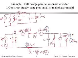
Example: Full-bridge parallel resonant inverter 1. Construct steady-state plus small-signal phasor model. Example: Full-bridge parallel resonant inverter 2. Steady-state solution. Example: Full-bridge parallel resonant inverter 3. Small-signal perturbation in output phasor.

E N D
Example: Full-bridge parallel resonant inverter1. Construct steady-state plus small-signal phasor model
Example: Full-bridge parallel resonant inverter2. Steady-state solution
Example: Full-bridge parallel resonant inverter3. Small-signal perturbation in output phasor
Example: Full-bridge parallel resonant inverter3. Small-signal perturbation in output phasor
Example: Full-bridge parallel resonant inverterSPICE-compatible model
parallel resonant inverter *PARAMETERS AND NODESETS *main circuit parameters .param L=627u .param Cp=7.9n .param Vg = 150 .param R=400 .param fs=86k .param ws=540k; .param Vin = 191 *steady-state switching frequency .nodeset v(w)=540k *voltages and currents .nodeset i(L_re)=0.5209 .nodeset i(L_im)=-0.8382 .nodeset v(out_re)=-92.99 .nodeset v(out_im)=-176.5 .nodeset v(outi)=0.6536 .nodeset v(outv)=199.5 .nodeset v(in_im)=0 .nodeset v(in_re)=191 .nodeset v(xl_im)=0 .nodeset v(xl_re)=191 .nodeset v(in_rex)=191 .nodeset v(out_imdum)=0 .nodeset v(out_redum)=0 *EXTRACT ENVELOPE Evout outv 0 value {sqrt(v(out_re)*v(out_re)+v(out_im)*v(out_im))} Rvout outv 0 100 Eiout outi 0 value {sqrt(i(vdum_re)*i(vdum_re)+i(vdum_im)*i(vdum_im))} Riout outi 0 100 *analysis setup .op .ac dec 201 1000 300k *.tran 1n 500u 0 0.1u .probe .END *CIRCUIT CONSTRUCTION *real part V_re in_rex 0 dc 191 ac 0 V_rex in_re in_rex sin(0 0 1000 0 0) ac 0 L_re in_re xl_re {L} EXL_re xl_re out_re value {-v(w)*{L}*i(EXL_im)} Cp_re out_re 0 {Cp} Gcp_re out_re 0 value {-v(w)*{Cp}*v(out_im)} Rp_re out_re 0 10g *add dummy voltage to measure current vdum_re out_re out_redum 0 R_re out_redum 0 {R} *imaginary part V_im in_im 0 dc 0 ac 0 L_im in_im xl_im {L} EXL_im xl_im out_im value {v(w)*{L}*i(EXL_re)} Cp_im out_im 0 {Cp} Gcp_im out_im 0 value {v(w)*{Cp}*v(out_re)} Rp_im out_im 0 10g *add dummy voltage to measure current vdum_im out_im out_imdum 0 R_im out_imdum 0 {R} *frequency perturbation vw w 0 {ws} ac 1 Rph w 0 1meg