High Power Beam Dump Hall A
210 likes | 448 Views
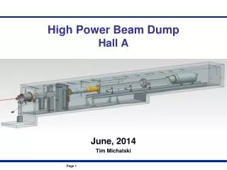
High Power Beam Dump Hall A. June, 2014 Tim Michalski. Overall Hall Dump Requirements. Helium Tube. Helium Purge. Helium Fill. BPIC / Flange Spacer (Optional). High Power Viewer.

High Power Beam Dump Hall A
E N D
Presentation Transcript
High Power Beam DumpHall A June, 2014 Tim Michalski
Helium Tube Helium Purge Helium Fill BPIC / Flange Spacer (Optional)
High Power Viewer .010” Thick Aluminum viewer screen – coated with .001”-.002” thick layer of aluminum oxide ceramic (grey alumina) – Mounted to mirror box for alignment and stability Flange w/ coated window – prevents N2 from back-flowing into hall
Diffuser Thickness Determination • Low Energy – no diffuser • 3 additional RL thickness diffuser segments • Covers full beam energy spectrum with overlap • Will require assessment during ERR
Diffuser • 4 position settings – set in the hall • Stacked aluminum plates – weight, cost, ease of manufacture • Oscillates at .1 Hz to distribute power density • Supplemental forced convection cooling for robust, long life • Graphalloy bearings – no lubricant for survival in radiation environment • Storage in lead block shielding when accessing past the Isolation Wall • Re-use existing stands to support the diffuser and shielding blocks
Diffuser, Vac Window, Aperture Plate Cooling • Forced Convection – Diffuser and Vacuum Window • Perimeter Water Cooling – Vacuum Window and Aperture Plate
Isolation Wall Looking Upstream Looking Downstream
Vacuum Window – Analysis Parameters • Goal to keep material stress below yield strength of 5052-O • 200 W/m2K forced convection on exterior face • Evaluate beam current vs spot size vs stress limits
Vacuum Pipe Design Details Vacuum Window – water cooled 45” Flange Interface Aperture Plate w/ 3” Center Hole – water cooled Calibration “Puck” – 1mm thick Tungsten Tune-Mode Viewer
Vacuum Pipe Vacuum Analysis • Analyzed for Vacuum and Buckling • BUCKLING: • Requires stiffening ribs to get to a SF=2 • Recommend stiffening ribs and an increased wall thickness to .188” (SF=3) VACUUM: Stress and displacement are acceptable at .125” wall thickness 5052-O Aluminum
Aperture Plate • 5% Target, 1 GeV, 200 uA – 1571 W • Worst Case • Also evaluated: • 10% Target, 1 GeV, 200 uA • 1% Target , 1 GeV, 200 uA • .5% Target, 1 GeV, 200 ua
Status / Schedule • Goal to have all material here by end of July • By end of this week, all material on order except diffuser parts and isolation wall • Vacuum Pipe due July 17th • Leaking dump flange repaired last week – need to leak test with 1st section of He pipe • Facilities has a plan for N2 generation and modified exhaust system – need schedule details • Modification and reassembly of He pipe complete by end of July • Diffuser, isolation wall, viewers, vacuum pipe installation planned for August • Installation of PSS, FSD, I&C, monitoring, EPICS screens - Sept