Download
1 / 20
210 likes | 465 Views
Seismic Performance Factors for Steel-Concrete Composite Frame Structures. Mark D. Denavit University of Illinois at Urbana-Champaign Urbana, Illinois Jerome F. Hajjar Northeastern University Boston, Massachusetts . Roberto T. Leon Virginia Polytechnic Institute and State University

E N D
Seismic Performance Factors for Steel-Concrete Composite Frame Structures • Mark D. Denavit • University of Illinois at Urbana-Champaign • Urbana, Illinois • Jerome F. Hajjar • Northeastern University • Boston, Massachusetts Roberto T. Leon Virginia Polytechnic Institute and State University Blacksburg, Virginia Sponsors: National Science Foundation American Institute of Steel Construction Georgia Institute of Technology University of Illinois at Urbana-Champaign Quake Summit 2012 Boston, Massachusetts July 12, 2012
Composite Column Steel Girders Seismic Performance Factors for Composite Frames • NEESR-II: System Behavior Factors for Composite and Mixed Structural Systems • FEMA P695 - Quantification of Building Seismic Performance Factors • Two seismic force resisting systems as defined in the AISC Seismic Specification • Composite Special Moment Frames (C-SMF) • Composite Special Concentrically Braced Frames (C-SCBF)
Mixed Beam-Column Element • Mixed formulation with both displacement and force shape functions • Total-Lagrangian corotational formulation • Distributed plasticity fiber formulation: stress and strain modeled explicitly at each fiber of cross section • Perfect composite action assumed (i.e., slip neglected) • Implemented in the OpenSees framework
Uniaxial Cyclic Constitutive Relations Steel Concrete Based on the rule-based model of Chang and Mander (1994). Tsai’s equation used for the monotonic backbone curve The confinement defined separately for each cross section • Based on the bounding-surface plasticity model of Shen et al. (1995). • Modifications were made to model the effects of local buckling and cold-forming process
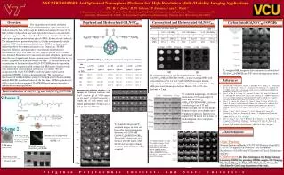
WF Cyclic Local Buckling CalibrationTsai and Popov 1988 W18x40; Fy = 310 MPa; h/tw = 50.9; bf/2tf = 5.73 W21x44; Fy = 333 MPa; h/tw = 56.3; bf/2tf = 7.22
Connection Regions in Special Moment Frames Nonlinear Column Element Zero Length Spring Representing the Panel Zone Shear Behavior Rigid Links Nonlinear Beam Element Elastic Beam Element
Connection Regions in Special Concentrically Braced Frames Nonlinear Column Element Moment Release Nonlinear Beam Element Rigid Links Nonlinear Brace Element
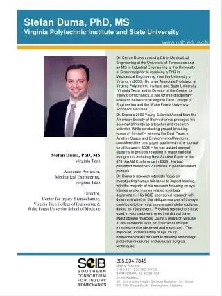
WF ValidationRicles, Peng, and Lu 2004 Column: H = 406 mm; B = 406 mm; t = 12.5 mm; Fy = 352 MPa; f′c = 58 MPa; P/Pno = 0.18; Beam: W24x62; Fy = 230 MPa; h/tw = 50.1; bf/2tf = 5.97
Nonlinear Analyses • Gravity load and mass defined as 1.05 D + 0.25 L • Rayleigh damping defined equal to 2.5% of critical in the 1st and 3rd mode • Modeling does not include: • Fracture • Connection degradation • Lateral torsional buckling
Evaluation of Seismic Performance Factors Archetype frames are categorized into performance groups based on basic structural characteristics
System Overstrength Factor, Ωo • By the FEMA P695 methodology, Ωo should be taken as the largest average value of Ω from any performance group • Rounded to nearest 0.5 • Upper limits of 1.5R and 3.0 • High overstrength for C-SMFs • Displacement controlled design • Current value (Ωo = 3.0) is upper limit and is acceptable • Overstrength for C-SCBFs near current value (Ωo = 2.0) • Higher for PG-3 and PG-4 (High gravity load, SDC Dmin)
Response Modification Factor, R By the FEMA P695 methodology, the R factor assumed in the design of the frames is acceptable if: • the probability of collapse for maximum considered earthquake ground motions is less than 20% for each frame • and less than 10% on average across a performance group.
Response Modification Factor, R • ACMR10% = 1.96 for both C-SMF and C-SCBF • ACMR values show correlation with the overstrength • C-SMFs • Current value (R = 8.0) is acceptable • C-SCBFs • Current value (R = 5.0) is acceptable
Deflection Amplification Factor, Cd • By the FEMA P695 methodology, Cd = R for these systems • Would represent a minor change for C-SCBF • Current values: Cd = 4.5, R = 5.0 • Typically strength controlled design • Would represent a significant change for C-SMF • Current values: Cd = 5.5, R = 8.0 • Typically displacement controlled design • Four C-SMF archetype frames designed with the current Cd value • Lower overstrength with current Cd • Acceptable performance with current Cd
Conclusions • Steel-concrete composite frames shown to exhibit excellent seismic behavior • Current seismic performance factors for C-SMF and C-SCBF found to be acceptable • Further investigation of the need for and effects of setting Cd equal to R is warranted for C-SMF