
Installing and Operating a System
E N D
Presentation Transcript
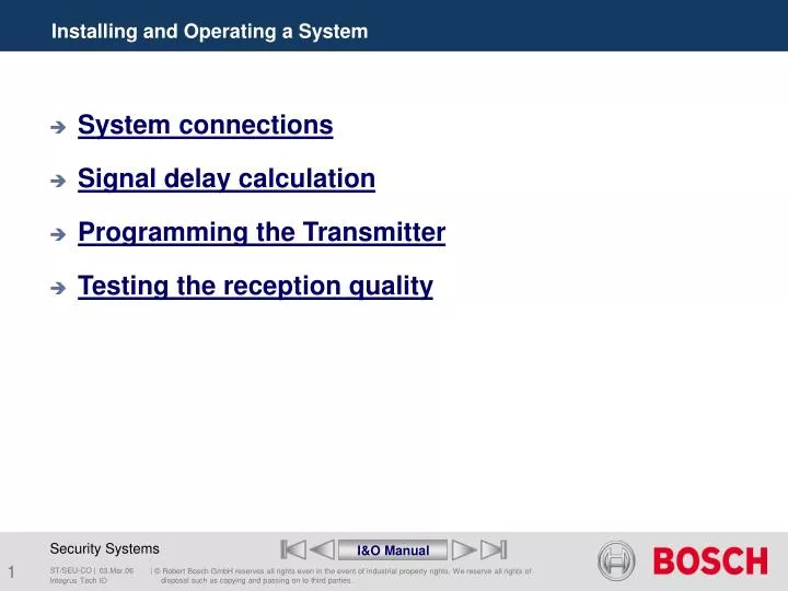
Installing and Operating a System • System connections • Signal delay calculation • Programming the Transmitter • Testing the reception quality I&O Manual Integrus Tech IO
Connecting the DCN Next Generation system • The transmitter can be directly connected to the optical network of the DCN Next Generation conference system by means of an optical network cable • Network mode must be enabled Integrus Tech IO
Connecting the DCN system • The transmitter requires the DCN Interface Module • The connections between DCN units and the transmitter are made in a loop-through configuration. Integrus Tech IO
DCN interface module • For interfacing with DCN • Allows simultaneous interpretation generated by DCN • LBB3423/20 Integrus Tech IO
Connecting the CCS800 and Interpreter desks • The transmitter requires the Symmetrical Audio Input and Interpreters Module. • Up to 12 6-Channels interpreter desks can be loop-through connected to the module. • The floor signal for the interpreters desk is connected to the Aux-Left input of the transmitter. • The floor signal from a CCS 800 discussion system line output or from an external audio source, such as an audio mixer. Integrus Tech IO
Symmetrical Audio Input Module • For use with analogue audio systems with 8 symmetrical Inputs • Up to 12 6-Channels interpreter desks LBB3222/04 • Automatic floor selection for unused interpretation channels • LBB3422/20 Integrus Tech IO
T T T T T T T T T=optional (Beyer type TR/BV3) Symmetrical Audio Input Module Integrus Tech IO
Settings on the Audio Input Module • Floor audio connection from CPSU line output to Aux. input of infra-red transmitter Integrus Tech IO
Maximum cable length to interpreters’ desks • Maximum Up to 12 6-Channels interpreter desks can be loop-through connected to the module. Integrus Tech IO
1 14 4 18 2 16 5 17 7 19 8 22 6 20 11 23 9 21 3 15 24 25 12 13 10 1 14 4 18 2 16 5 17 7 19 8 22 6 20 11 23 9 21 3 15 24 25 12 13 10 I n t e r p r e t e r ‘s D e s k Audio 1 input OR Floor Channel Audio 2 input Channel 1 Audio 3 input Channel 2 Audio 4 input Channel 3 Audio 5 input Channel 4 Audio 6 input Channel 5 Audio 7 input Channel 6 Audio 8 input Busy in Audio Comm Comm. Audio AF OR2 Auto Relay Supply (+27V) Supply (+27V) Supply (+12V) Supply (+12V) Ground Ground Supply(-12V) Supply(-12V) Earth Earth 3,3uF/25V FL. CH.1 CH.2 CH.3 CH.4 CH.5 CH.6 Interface connection to Recording System LBB3422/20 Symmetrical Audio Input Module LBB3222/04 6-Channel Interpreter’s Desk To be made locally To recording system Integrus Tech IO
Connecting other external audio sources • The audio signals (stereo or mono) are connected to the audio input cinch connectors. • When the cinch audio inputs are used in combination with inputs via one of the interface modules, the signals on corresponding channels are mixed. Integrus Tech IO
Connecting an emergency signal switch • To use the emergency signal function, a switch (normally-open) must be connected to the emergency switch connector. • When the switch is closed, the audio signal on the Aux-right input is distributed to all output channels, overriding all other audio inputs. • The Aux. Input mode of the transmitter must be set to ‘Mono + Emergency’ Integrus Tech IO
Connecting to another transmitter • The transmitter can operated in slave mode to loop-through the IR radiator signals from a master transmitter. • One of the six radiator outputsof the master transmitter is connected with an RG59 cable to the radiator signal loop-through input of the slave transmitter. • The Transmission mode of the slave transmitter must be set to ‘Slave’ Integrus Tech IO
Connecting radiators to transmitter • The transmitter has six BNC connectors on the rear panel. They can each drive up to 30 radiators in a loop-through configuration. • The radiators are connected with RG59 cables (75 Ohm). • The maximum cable length per output is 900 m. • Automatically cable termination by a built-in detection circuit. Integrus Tech IO
Connecting radiators to transmitter • Notes: • Never leave an open-ended cable connected to the last radiator in a loop-through chain. • When connecting infra-red radiators, do not split the cable, else the system will not function correctly. Integrus Tech IO
Signal delay calculation • Setting the radiator delay compensation switches • Differences in cable length between the transmitter and the radiators can cause black spots as a result of the multipath effect. • The IR signal from a radiator with a long cable is delayed with respect to the signal from a radiator with a shorter cable. • To compensate these cable length differences, the delay of a radiator can be increased to make it equal to the signal delay of the other radiators. • This signal delay can be set with delay switches at the back of the radiator. Integrus Tech IO
Signal delay calculation • Two ways for determining delay compensation switch positions of the radiator. • By measuring the cable lengths 1.1 Manual 1.2 delay switch calculation tool (recommended) • By using a delay measuringtool 2.1 Manual 2.2 delay switch calculation tool (recommended) Integrus Tech IO
Signal delay calculation 1.1 • To determine the delay switch position based on cable lengths and calculating manually follow the next steps: • Measure the lengths of the cables between the transmitter and each radiator. • Multiply these cable length differences with the cable signal delay per meter (the manufacturer specified factor). This is the cable signal delay difference for that radiator. • Determine the maximum signal delay. • Calculate for each radiator the signal delay difference with the maximum signal delay. • Divide the signal delay difference by 33. The rounded off figure is the signal delay switch position for that radiator. • Set the delay switches to the calculated switch positions. Cable Measuring Integrus Tech IO
Transmitter Signal delay calculation 1 Integrus Tech IO
Signal delay calculation 1.2 • To determine the delay switch position based on cable lengths and the delay switchcalculation tool follow the next steps: • Start the calculation tool • Select system type • Fill-in the cable signal delay per meter of the used cable. (specified by the cable manufacturer). • Fill-in the number of radiator(s) on each output • Fill-in the measured cable lengths of the cables between the transmitter and each radiator. • Set the delay switches on the radiator(s) to the automatically calculated switch positions. Calculation tool Integrus Tech IO
Signal delay calculation 2.1 • To determine the delay switch position by delay measuring tooland calculating manually follow the next steps: • Disconnect the cable from a radiator output of the transmitter and connect this to a delay measurement tool. • Disconnect the cable from the first radiator in that trunk. • Measure the impulse response time (in ns) of the cable(s) between that transmitter and the radiator. • Reconnect the cable to the radiator and repeat steps 2 to 4 for the other radiators (started by the next radiator in that trunk). • Reconnect the cable to the transmitter and repeat step 2 to 5 for the other radiator outputs of the transmitter. • Divide the impulse response times for each radiator by two. These are the cable signal delays for each radiator. Integrus Tech IO
Signal delay calculation 2.1 • Determine the maximum signal delay. • Calculate for each radiator the signal delay difference with the maximum signal delay. • Divide the signal delay difference by 33. The rounded off figure is the delay switch position for that radiator. • Set the delay switches to the calculated switch positions. Delay Measuring Integrus Tech IO
584 ns 350 ns Transmitter 237 ns 563 ns 339 ns Signal delay calculation 2.2 Integrus Tech IO
Signal delay calculation 2.2 • To determine the delay switch position by delay measuringtooland the delay switchcalculation tool the follow the next steps: • Start the calculation tool, Select system type, Fill-in the number of radiator(s) on each output • Disconnect the cable from a radiator output of the transmitter and connect this to a delay measurement tool. • Disconnect the cable from the first radiator in that trunk. • Measure the impulse response time (in ns) of the cable(s) between that transmitter and the radiator. • Enter this impulse response time in the calculation tool. • Reconnect the cable to the radiator and repeat steps 2 to 4 for the other radiators (started by the next radiator in that trunk). Calculation tool Integrus Tech IO
Signal delay calculation 2.2 • Reconnect the cable to the transmitter and repeat step 2 to 5 for the other radiator outputs of the transmitter. • When the cable signal delays are known, the delay switch calculation tool will calculate the delay switch positions automatically. Calculation tool Integrus Tech IO
Signal delay calculation with more transmitters • When radiators in one multi purpose room are connected to two transmitters, an extra signal delay is added by: • Transmission from master transmitter to slave transmitter (cable signal delay). • Transmission through the slave transmitter. Calculation tool Integrus Tech IO
Signal delay calculation with more transmitters • For calculating the delay switch positions for a system with a master-slave configuration, use the following procedure: • Calculate the cable signal delay for each radiator, using the procedures for a system with one transmitter. • Calculate the signal delay of the cable between the master and the slave transmitter in the same way as for cables between a transmitter and a radiator. • Add to the cable signal delay of the cable between the master and the slave, the delay of the slave transmitter itself: 33 ns. This gives the master-to-slave signal delay. • Add the master-to-slave signal delay to each radiator connected to the slave transmitter. • Determine the maximum signal delay. Calculation tool Integrus Tech IO
Signal delay calculation with more transmitters • Calculate for each radiator the signal delay difference with the maximum signal delay. • Divide the signal delay difference by 33. The rounded off figure is the signal delay switch position for that radiator. • Set the delay switches to the calculated delay switch positions. Calculation tool Integrus Tech IO
R10 R7 R5 R2 20m 20m 20m 20m R3 R8 R1 R9 R6 R4 30m 30m 30m 30m 20m 20m Signal delay calculation with more transmitters 50m Tx Slave Tx Master Integrus Tech IO
Signal delay calculation with more transmitters Integrus Tech IO
Radiation signal delay • A situation in which a radiation signal delay occurs. • For systems with more than four carriers, add one delay switch position per 10 meter difference in signal path length to the radiators which are closest to the overlapping coverage area. • In this Figure the signal path length difference is 12 meter. Add one delay switch position to the calculated switch position(s) for the radiator(s) under the balcony. Calculation tool Integrus Tech IO
Transmitter Status Fault Status Monitoring Enquiry 3 2 1 0 4 < Setup Back Transmitter menu structure I&O Manual Integrus Tech IO
Transmitter Status Fault Status Source and Volume Monitoring Enquiry 1 0 3 2 4 < Setup Back 2A Transmitter menu structure I&O Manual Integrus Tech IO
Transmitter Status SW Version FPGA Version Fault Status HW Version Serial Number Monitoring Enquiry 3 2 1 0 4 < Setup Back 3C 3B 3A 3D Transmitter menu structure I&O Manual Integrus Tech IO
Transmitter Status Aux. Input Mode 4P Defaults 4N Mini Radiator on/off Channel Name 4G Fault Status 4O Headphone on/off Carrier Settings Sensitivity Inputs Language List Channel Quality 4M Unit Name Number of Channels Sensitivity Aux. Left Network Mode Monitoring 4H 4A Transmission Mode Carrier Overview Enquiry 2 1 0 3 Sensitivity Aux. Right < 4 Setup Back 4F 4K 4C 4B 4J 4L 4D 4I 4E Transmitter menu structure I&O Manual Integrus Tech IO
Testing the reception quality • An extensive reception quality test must be done to make sure that the whole area is covered with IR radiation of adequate strength. Such a test can be done during installation and during the meeting: • Test during installation: • Check that all radiators are connected and powered up and that no loose cables are connected to a radiator. Switch the transmitter off and on. (needed for the auto signal equalisation) • Set the transmitter in the Test-mode. For each channel a different frequency test tone will be transmitted. • Set a receiver on the highest available channel and listen via the headphones to the transmitted test tone. • For testing all positions follow the instruction of chapter 1.6 of the Integrus ‘Installation and Operating Instructions’ Integrus Tech IO
Testing the reception quality • Testing during the meeting: • Set a receiver in the Test-mode and select the highest available carrier. The quality of the received carrier signal is indicated on the display of the receiver. • The quality indication should be between 00 and 39 (good reception). • For testing all positions follow the instruction of chapter 1.6 of the Integrus ‘Installation and Operating Instructions’ Integrus Tech IO
Installing and Operating a System End of section Integrus menu Integrus Tech IO