Download
1 / 21
210 likes | 364 Views
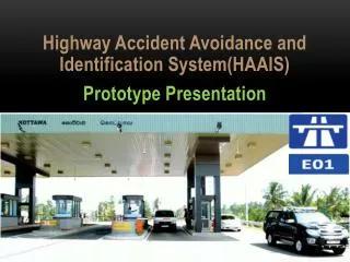
Highway Accident Avoidance and Identification System(HAAIS) Prototype Presentation. Introduction……. System Diagram. Current Progress……. Vehicle Device. Small and user-friendly device. Rechargeable power source . Ability to interact with a bar code reader. Integrated with Xbee RF modules.

E N D
Highway Accident Avoidance and Identification System(HAAIS) Prototype Presentation
Vehicle Device • Small and user-friendly device. • Rechargeable power source . • Ability to interact with a bar code reader. • Integrated with Xbee RF modules. • 70% completed
Vehicle Device • Circuit Design Done • Circuit Implementation 80 % Done • Microcontroller Programming code 70 %Done • Xbee Programing Code Done • Vehicle Device Structural ImplementationRemaining • Testing Remaining • Integration Remaining
Road Device • Circuit Design Done • Circuit Implementation Done • Microcontroller Programming code 60 %Done • Xbee Programing Code Done • Road Device Structural Implementation Remaining • Testing Remaining • Integration Remaining
Xbee Programming code for VD & RD RF Modules +++ Enter configuration mode (Default) atdlFFFF Set/Read the lower 16 bits of the 32-bit destination address. atmy0010 Set/Read the lower 16 bits of the 32-bit destination address. atir02 Set/Read sample rate. atwrWrite parameter values to nonvolatile memory so that parameter modifications persist through subsequent power-up or reset.
Vehicle ID Structure V 10 224 V A---Z =22 22 + 10 = 32 256-32=224 Calculating Error check byte 0x56 0x0A 0xE0 Error Check byte VD Xbee Module Source address Message type
Road Device SMS Message Structure R A---Z =18 18 + 25 = 43 43 + 10=53 256-53=203 Calculating Error check byte R 25 10 203 0xCB 0x01 0x19 0x0A Error Check byte VD Xbee Module Source address Road Device Number Message type
Software User Interfaces • Entrance System 90% Done • Exit System 80% Done • Emergency Notify System 10% Done • Testing • Unit Testing 50% Done • Integration Testing Remaining
Server System…… • Server Architecture Done • Server Software • Designing Done • Implementing Done • Developing 90% • Database • Query Implementation and Developing Done • Ozeki SMS Gateway 60% • Testing Remaining • Integration Remaining