Download
1 / 20
200 likes | 327 Views
Stereoscopic Imaging for Slow-Moving Autonomous Vehicle. Senior Project Progress Report Bradley University ECE Department. By: Alex Norton Advisor: Dr. Huggins February 28, 2012. Presentation Outline. Review of Proposed Project Project Overview Original Proposed Schedule

E N D
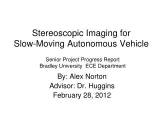
Stereoscopic Imaging for Slow-Moving Autonomous Vehicle Senior Project Progress Report Bradley University ECE Department By: Alex Norton Advisor: Dr. Huggins February 28, 2012
Presentation Outline • Review of Proposed Project • Project Overview • Original Proposed Schedule • Tasks Completed • Webcams setup • Calibration mode software • Remaining Tasks • Run mode software • Improve existing software • Revised Schedule
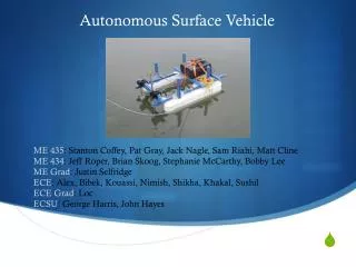
Project Overview • Two horizontally aligned, slightly offset cameras taking a pair of images at the same time • By matching corresponding pixels between the two images, the distances to objects can be calculated using triangulation • This depth information can be used to create a 3-D image and terrain map
Tasks Completed Webcams setup • Creates “capture” objects for both webcams • Takes a set of images each time the “enter” key is pressed • Displays the saved set of images in two windows • Saves the images to a specified folder to use for further image processing
Necessity of Calibration • Produces the rotation and translation matrices needed to rectify sets of images • Rectification makes the stereo correspondence more accurate and more efficient • Failing to calibrate the cameras is a possible reason for why past groups have failed to get accurate results
Calibration Mode Software • Input is a list of sets of images of a chessboard, and the number of corners along the length and width of the chessboard • Read in the left and right image pairs, find the chessboard corners, and set object and image points for the images where all the chessboards could be found • Given this list of found points on the chessboard images, the code calls cvStereoCalibrate() to calibrate the cameras
Calibration Mode Software • This calibration gives us the camera matrix M and the distortion vector D for the two cameras; it also yields the rotation matrix R, the translation vector T, the essential matrix E, and the fundamental matrix F • The accuracy of the calibration is assessed by checking how nearly the points in one image lie on the epipolar lines of the other image
Calibration Mode Software • The code then moves on to computing the rectification maps using Bouguet’s method with cvStereoRectify() • The rectified images are then computed using cvRemap() • The disparity map is then computed by using cvFindStereoCorrespondenceBM()
Calibration Mode Software • Two methods for stereo rectification • Hartley’s Method: uses the fundamental matrix, does not require the cameras to be calibrated, produces more distorted images than Bouguet’s method • Bouget’s Method: uses the rotation and translation parameters from two calibrated cameras, also outputs the reprojection matrix Q used to project two dimensional points into three dimensions
Calibration Mode Software Matrices • Rotation matrix R, Translation Vector T : extrinsic matrices, put the right camera in the same plane as the left camera, which makes the two image planes coplanar • Fundamental matrix F: intrinsic matrix, relates the points on the image plane of one camera in pixels to the points on the image plane of the other camera in pixels
Calibration Mode Software Matrices • Essential Matrix E: intrinsic matrix, relates the physical location of the point P as seen by the left camera to the location of the same point as seen by the right camera • Camera matrix M, distortion matrix D: intrinsic matrices, calculated and used within the function
Calibration Mode Software Example of bad chessboard image
Calibration Mode Software Output when bad chessboard images are run through the calibration software
Calibration Mode Software Example of good chessboard image
Calibration Mode Software Output when good chessboard images are run through the calibration software
Remaining Tasks • Use triangulation to determine distances to objects • Calculate the error in the distance measurements • Minimize the error in both the camera calibration and the distance measurements