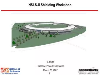
Shielding Workshop for Diagnostic Imaging
Shielding Workshop for Diagnostic Imaging. Professor Jim Malone Trinity College, Dubin Robert Boyle Foundation. Overview of posible topics. A Few CONTEXT Issues Five Step Shielding Calculations Leading questions, Socratic Method. Context: Equipment.

Shielding Workshop for Diagnostic Imaging
E N D
Presentation Transcript
Shielding Workshop for Diagnostic Imaging Professor Jim Malone Trinity College, Dubin Robert Boyle Foundation
Overview of posible topics • A Few CONTEXT Issues • Five Step Shielding Calculations • Leading questions, Socratic Method
Context: Makes Problems for Facility Design • Changes in Legislation, Technology, Clinical Practice, Building Style, Building Materials • On whose behalf are you working? Hospital management or the public interest? • Changes in Dose Limits and Constraints • Practical Tips and Solutions
Context: New Problems • Walls not always solid • Use of Upper Floors • Ceilings, Floors, Higher levels of walls • Theatre workloads not consistent with modern practice. • Other – recovery rooms, endo suites, lithotripsy, cardiac pacing • Radionuclides in Theatres
Context: Medical Physics Medical Physics Support • Deficits in numbers, leadership and academic involvement/connectivity • Often poor, or inadequate training, and narrow or inadequate experience • Research Output: Poor to None • Risk of litigation and difficulties with public accountability
Published, 1988. www.rpii.ie Revised, 2009. RPII, 3 Clonskeagh Square, Dublin 14, Ireland
Five Step Shielding Calculations • Identify boundary to be shielded • Determine design dose to be achieved beyond the boundary • Estimate the dose/dose rate before the boundary • Read the shielding required to attenuate dose in 3 to dose in 2 from graphs or tables • Practical Implementation issues
Dose Limits and Constraints Design Limit is generally not a matter of Discretion, it is usually prescribed by law of formal advice.
DOSE CONSTRAINTS • Prospective; Used in Planning; Verifiable retrospectively. • (EU BSS, 96/29) Definition: -- A restriction on the prospective dose to individuals which may result from a defined source, for use in the planning stage in radiation protection whenever optimization is involved. • Article 7: • Should be used when appropriate, within optimization • May be in Guidance established by member states. • In many regulatory documents (BSS/EU)
Occupancy • Occupancy of adjoining areas to be assessed • Try and get real information • Consider rooms on other side of corridor • Extremes: Office, 100%; Unattended car-park, 2.5 to 5 % • Reservation about NCRP door value in new builds, and Remember: • Transparency and accountability to the public • Defendable legally (reasonable patient, not doctor or physicist)
Clear Mind and Objectives • We have to be clear on what the design objective is; • Everything else flows from it • Public demands transparency and accountability • The rest is science
Two Types of Radiation • Primary Beam: • Collimated from the x-ray tube. Intercepted by the patient, image receptor and some beam-stopping heavy shielding. • In a well designed facility, now seldom a problem. • Scatered or Secondary Radiation: • Main source is the patient, and is normally main source of radiation in a room.
Dose/dose rate before boundary • Primary often not an issue outside of plain radiography and mobiles
Scattered Radiation • When X-Ray beam interacts with the patient some is scattered (Compton). • Room shielded to protect those outside it, ie, workers, the public, other patients et al. • Level of shielding required depends on many factors, including the type of equipment. Also the distance (i.e. room size), workload in room, and adjacent occupancy.
Workload and Shielding Calculations • BIR: Workload is mainly based (ESD) and (DAP) • NCRP: Workload based on “beam-on” time. in mA min per week X-Ray • Two widely used Methodologies • BIR, 2000 • NCRP, 2004 • Variables • Distance from Barrier • Workload • Occupancy Issue of New Build versus Conversion/Refit
Workload • Either DAP (BIR) or mA-min/week (NCRP) • Try and base figures on real information, audit/projection • Historical or published data can mislead • If no other option, use published data • Transparency/accountability to public • Defendable legally (reasonable patient, not reasonable doctor)
Room Design and Layout • Radiology Room Types • General Comments on Shielding • Radiography Rooms • General • Chest Room • Mammography • DXA • Dental • Fluoroscopy Rooms • General Fluoroscopy • Interventional Radiology and Cardiology • CT • Shared Function Rooms (A&E, Theatres, wards) • Equipment in Trailers
General Room • Two-corridor Design • Large enough for trolleys, table and chest radiology • Typical room sizes given • Generally 2mm Lead – assess on individual basis • Primary Beam absorber • Staff entrance behind protective screen • Typical screen lengths presented • Chest stand positioned to minimise scatter entering protective console • Changing cubicles Specific Requirements for each type of facility Examples of Good Layouts
Dental Surgery and CT Room Dental Surgery No shielding required if: < 20 exps/wk and 2m between patient and all boundaries CT Separate staff area – Other staff present Need good view of door and patient Scanner angled for access and visibility MSCT: 3-4mm Pb
Equipment not even in Building • Trailer • Re-shielding often means complete refit • Hospital can’t do without equipment for 6 months • Trailer arrives -----
CT Room Shielding • Early understanding – no shielding (1970s) • BIR/IPEM Report (2000) example 1.7mm Pb • NCRP Report 147 (2004) example 1.4mm Pb • NHS Estates (HBN 6, 2001), 3 - 4mm Pb
5.2 2.6 1.3 0.6 0.6 1.3 2.6 5.2 CT Isodose Profiles BIR / IPEM: “Radiation Shielding for Diagnostic X-rays”, Sutton D.G. and Williams J.R. (2000) Scatter Profile (μSv/100mAs/20mm Slice)
1. Superimpose Scatter profile on Plans. Find dose at boundaries 2.6μSv
Ceiling 5.2 Floor Similarly for Ceiling, Floor & Windows
5.2 Gantry Tilt may increase exposure of ceiling floor
2. Multiply Boundary Dose • by CT Workload. • Typical Exposure Factors • Head: 120kVp, 350mAs, 15cm • Body: 120kVp, 250mAs, 40cm 130μSv / body scan
2. Multiply Boundary Dose • Workload. • Typical Exposure Factors • Head: 120kVp, 350mAs, 15cm • Body: 120kVp, 250mAs, 40cm • (b) Workload, eg.100 per week 650mSv / year
3. Find Target Dose in Adjacent areas. • Target Dose – 0.3mSv (BIR / IPEM) • Occupancy (BIR / IPEM) Corridor, 20%, 1.5mSv Control Room, 100% 0.3mSv Office 100% 0.3mSv Ward 20% 1.5mSv
4. Find Maximum Transmission for each Boundary 0.3mSv / 650mSv =5x10⁻⁴
5. Find thickness of lead / concrete (not Barium) 1x100 BIR/IPEM Report Secondary Transmission 150kVp 1x10⁻¹ Attenuation 1x10⁻² 1x10⁻³ 1x10⁻⁴ 1x10⁻⁵ 2 1 3 4 0 Lead thickness (mm)
General Radiographic Room Ceiling (NCRP method) General Rm Window, scatter only, at 10 m
6. Practical Considerations • Walls • Floors and Ceilings • Doors • Windows • Staff Areas • Joints, Services, Openings and Perforations • Assessment of Shielding • Nuclear Medicine • Building Materials • Lead sheet and lead products • Concrete and concrete Blocks • Barium Plaster • Brick • Gypsum Wallboard • Lead Glass • Lead Acrylic ALWAYS NEED TO VISIT AND SEE IMPLEMENTATION