Download
1 / 8
90 likes | 257 Views
Chapter 10 Analog Integrated Circuits The 741 OP-AMP Introduction.

E N D
Chapter 10 Analog Integrated Circuits The 741 OP-AMP Introduction
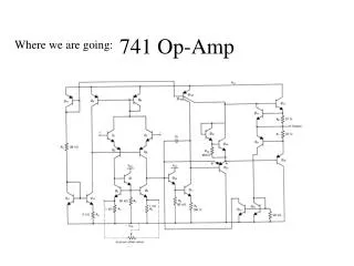
Fig. 10.1 The 741 op-amp circuit. Q11, Q12, and R5 generate a reference bias current, IREF, Q10, Q9, and Q8 bias the input stage, which is composed of Q1 to Q7. The second gain stage is composed f Q16 and Q17 with Q13 acting as active load. The class AB output stage is formed by Q14 and Q20 with biasing devices Q18 and Q19 and an input buffer Q23. Transistors Q15, Q21, Q24, and Q22 serve to protect the amplifier against output short circuit and are normally off.
Bias Circuit Short-Circuit Protection
Input Stage The Second Stage The Output Stage Device Parameters
The DC Analysis of the 741 Fig. 10.3 The dc analysis of the 741 input stage.
Small-Signal Analysis of the 741 Input Stage Fig. 10.6 Small-signal analysis of the 741 input stage
Fig. 10.7 The load circuit of the input stage fed by the two complementary current signals generated by Q1 through Q4 in Fig. 10.6. The order of the analysis steps is indicated by the circled numbers.