Download
1 / 26
260 likes | 375 Views
Les 7 - onderwerpen. Osiris A/D conversie Seriele communicatie met een PC. DB037 circuit – multiplexers. PIC – A/D. A/D converter vertaald een analoge spanning naar een waarde 0..255 (8 bits) of 0..1023 (10 bits). RA0 . PIC – A/D – configure pin as analog. PIC – A/D – aan zetten.

E N D
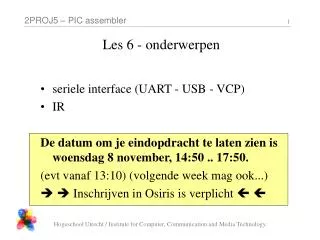
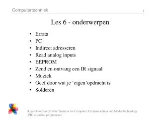
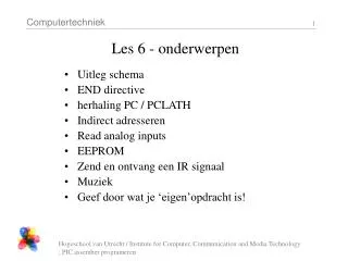
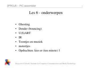
Les 7 - onderwerpen Osiris • A/D conversie • Seriele communicatie met een PC Hogeschool Utrecht / Institute for Computer, Communication and Media Technology
DB037 circuit – multiplexers Hogeschool Utrecht / Institute for Computer, Communication and Media Technology
PIC – A/D A/D converter vertaald een analoge spanning naar een waarde 0..255 (8 bits) of 0..1023 (10 bits) RA0 Hogeschool Utrecht / Institute for Computer, Communication and Media Technology
PIC – A/D – configure pin as analog Hogeschool Utrecht / Institute for Computer, Communication and Media Technology
PIC – A/D – aan zetten Hogeschool Utrecht / Institute for Computer, Communication and Media Technology
PIC – A/D – channel Hogeschool Utrecht / Institute for Computer, Communication and Media Technology
PIC – A/D – clock Hogeschool Utrecht / Institute for Computer, Communication and Media Technology
PIC – A/D – start, wait Hogeschool Utrecht / Institute for Computer, Communication and Media Technology
PIC – A/D – start, wait Hogeschool Utrecht / Institute for Computer, Communication and Media Technology
PIC – A/D – enable, go / done Hogeschool Utrecht / Institute for Computer, Communication and Media Technology
PIC – A/D – result format Hogeschool Utrecht / Institute for Computer, Communication and Media Technology
Read an analog input • Zet de juiste code op poort RE • Configureer de pin (RA0) als input (TRISA) • Configureer de pin (RA0 = AN0) in ANSEL als analoog • Activeer de A/D, selecteer het betreffende kanaal, selecteer de conversie clock (ADCON0) • Selecteer VSS en VDD als referenties, en de alignment (ADCON1) • wacht 100 us • start de conversie (ADCON0) • wacht tot de conversie voltooid is (ADCON0) • lees het resultaat (ADRESH, eventueel ADRESL) Hogeschool Utrecht / Institute for Computer, Communication and Media Technology
Opgave ‘A/D’ (facultatief) 1) Lees met de A/D converter de potentiometer uit en laat het 8-bits resultaat zien op 2 zeven-segment displays. 2) Lees met de A/D converter de LDR uit en laat het 8-bit resultaat zien op de LEDs Hogeschool Utrecht / Institute for Computer, Communication and Media Technology
PIC - USART USART = Universal Synchronous / Asynchronous Receiver + Transmitter • wij gebruiken asynchroon • PIC UART pins zijn verbonden met een FT232R USB-to-asynchronous converter • Op de PC wordt een (virtuele) seriele poort aangemaakt (XP heeft al een driver) control panel system hardware device manager ports • evt driver van www.ftdichip.com gebruiken • op de PC gebruik je een terminal, bv HyperTerminal (hypertrm, 19k2, no parity, no flow control, hu: com3) Hogeschool Utrecht / Institute for Computer, Communication and Media Technology
PIC - USART Hogeschool Utrecht / Institute for Computer, Communication and Media Technology
Hogeschool Utrecht / Institute for Computer, Communication and Media Technology
BRGH = 0 BRGH = 1 Hogeschool Utrecht / Institute for Computer, Communication and Media Technology
- 0 1 0 - 1 R - Hogeschool Utrecht / Institute for Computer, Communication and Media Technology
1 0 - 1 0 R R - Hogeschool Utrecht / Institute for Computer, Communication and Media Technology
PIC – USART - init make TxD (RC6) output, RxD (RC7) input SPBRG: 19k2 value for high speed TXSTA: 8 bit, enable, asynch, high speed RCSTA: enable, 8 bit, continuous, no ADDEN Hogeschool Utrecht / Institute for Computer, Communication and Media Technology
PIC – USART - send • wacht tot TSR bit aangeeft dat TSR empty is • copy het te verzenden byte naar TXREG • (wacht tot TSR bit aangeeft dat TSR empty is) Hogeschool Utrecht / Institute for Computer, Communication and Media Technology
PIC – USART - receive • als OERR bit gezet is: • clear CREN • wacht een paar instructies • set CREN • als PIR1 : TXIF op 0 gezet is: • lees RCREG, dit is het ontvangen byte (anders is er nog niets ontvangen) Hogeschool Utrecht / Institute for Computer, Communication and Media Technology
power van de 2e USB poort : jumper links Hogeschool Utrecht / Institute for Computer, Communication and Media Technology
PIC – USART – demo code subroutines UART_INIT : call to inistialise the UART for 19k2 UART_CHAR_SEND : sends the char in W UART_CHAR_RECEIVE : checks the UART for a received char, C flag set when a char is received (char in W), C flag is cleared when no char is received UART_CLRF_SEND : sends the CR LF sequence Hogeschool Utrecht / Institute for Computer, Communication and Media Technology
PIC – USART – demo code main MAIN CALL UART_INIT MOVLW 'H' CALL UART_CHAR_SEND MOVLW 'i' CALL UART_CHAR_SEND CALL UART_CLRF_SEND MAIN_LOOP CALL UART_CHAR_RECEIVE SKPC GOTO MAIN_LOOP MOVWF Char MOVLW '"' CALL UART_CHAR_SEND MOVFW Char CALL UART_CHAR_SEND MOVLW '"' CALL UART_CHAR_SEND CALL UART_CLRF_SEND GOTO MAIN_LOOP Hogeschool Utrecht / Institute for Computer, Communication and Media Technology
opdracht (facultatief): toetsenbord, A/D, display, UART Schrijf een programma dat het toetsenbord leest, en de ingedrukte toets laat zien op het meest linker display. De ingedrukte toets bepaald het A/D kanaal dat wordt gelezen, en (hexadecimaal) wordt weergegeven op de rechter 2 displays. Hogeschool Utrecht / Institute for Computer, Communication and Media Technology