Basic Coordinate Systems
Learn about various coordinate systems like State Plane, UTM, and Geographic systems to accurately describe locations. Explore how datum changes affect coordinates and the importance of scale factor.

Basic Coordinate Systems
E N D
Presentation Transcript
Basic Coordinate Systems Grid System RG 620 April 20, 2016 Institute of Space Technology, Karachi
Coordinates are not certain!! Even if their figures are precise
Example • In 1937 the United States Coast and Geodetic Survey set Youghall at latitude 40º 25' 33.504"N and longitude 108º 45' 55.378"W • In November of 1997Youghall suddenly got a new coordinate, 40º 25' 33.39258"N and 108º 45' 57.78374"W • Had Youghall actually moved at all? • Of course it did no such thing, the station is right where it has always been • Its datum changed !!!!!! • Originally, in1937 latitude and longitude for Youghall was based on the North American Datum 1927 • In 1997 the basis of the coordinate of Youghall became the North American Datum 1983 (NAD83)
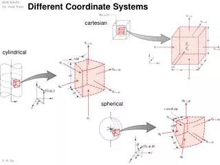
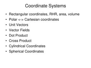
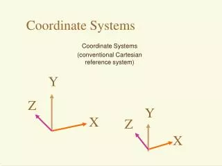
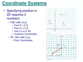
Coordinate Systems • After projection, it is necessary to set up a coordinate system on the map that will allow a point to be described in X-Y space (or northing and easting) • To describe a location in a universally understandable manner a grid system is necessary • For a useful grid it is necessary for it to define an origin and a uniform grid spacing • There are several types of Coordinate System to represent the Earth’s surface
Coordinate Systems • The method of projection, onto a simple flat plane, is based on the idea that a small section of the Earth, as with a small section of the orange, conforms so nearly to a plane that distortion on such a system is negligible • Mapping a considerable portion of the Earth using a large number of small individual planes • Offers the convenience of working in plane Cartesian coordinates and still keep distortion at manageable levels • Note: when these planes are brought together they cannot be edge-matched accurately
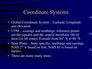
Coordinate Systems • Some commonly used Coordinate Systems are: • Geographic • Latitude and Longitudes are used • UTM • Shape is preserved and precise measurements in meter • State Plane • Local surveying (with minimum distortion)
State Plane Coordinate (SPC) Systems • Standard set of projections for the United States developed in 1930’s • Specifies positions in Cartesian coordinate systems for each state • Used for local surveying and engineering applications • Points are projected from their geodetic latitudes and longitudes to x and y coordinates in the State Plane systems • Conformal mapping system for US with a maximum scale distortion of 1 part in 10,000
State Plane Coordinate Systems • Zones have different projections • Lambert Conformal Conic: for states that are longer east–west, such as Tennessee, Kentucky, North Carolina, Virginia, etc. • Transverse Mercator projection: for states that are longer north–south, such as Illinois, Arizona, New Hampshire, etc. • The Oblique Mercator projection: for the panhandle of Alaska (AK zone 1) because it lays at an angle
State Plane Coordinate Systems • Large states are divided into zones to limit distortion error and maintain said accuracy • One or more zones in each state with slightly different projection in each zone • Boundaries of zones follow state and county lines • The number of zones in each state is determined by the area the state covers • The number of zones ranges from 1 to 10 (in Alaska) • Each zone has a unique central meridian
State Plane 1927 vs. 1983 • Originally based on the North American Datum of 1927 and the measurement unit was feet • Now being converted to North American Datum of 1983 (NAD83) (will use meters as unit of measure) • Due to datum change some zones are redefined
Scale Factor Where K is the scale factor for a line, K1 is the scale factor at one end of the line and K2 is the scale factor at the other end of the line.
Scale Factor • Scale factor varies with the latitude in the Lambert projection. • Distortion lessens and the scale factor approaches 1 as a line nears a ______??
Universal Transverse Mercator Coordinate System • Global coordinate system • Globe is divided into narrow longitude zones • Best used for north-south oriented areas (little distortion in this direction) • Successive swaths of relatively undistorted regions created by changing the orientation of the cylinder slightly • These swaths are called UTM zones • Each zone is six degrees of longitude wide • Total _?_____zones • Error is less than 0.04%
Universal Transverse Mercator Coordinate System • These zones are numbered from west to east • Zone 1 begins at the International Date Line (1800 W), Zone 2 at 174°W and extends to 168°W • Each Zone is further divided into Eastern and Western halves by drawing a center line called Central Meridian • Zones are further split north and south of the equator
Universal Transverse Mercator Coordinate System • At equator a zone is about 40,000/60 = 667 Km wide • Any point can be described by ‘Easting’ and ‘Northing’ values • Northing is the distance to the equator, while easting is the distance to the "false easting", which is uniquely defined in each UTM zone • The equator is used as the northing origin for all north zones (northing value of zero) • South zones have a false northing value added to ensure all coordinates within a zone are positive • For UTM south zones, the northing values at the equator are set to equal 10,000,000 meters
The UTM secant projection gives approximately 180 kilometers between the lines of exact scale where the cylinder intersects the ellipsoid (total = 360 km). The scale factor grows from 0.9996 along the central meridian of a UTM zone to 1.00000 at 180 km to the east and west. In state plane coordinates, the scale factor is usually no more than 1 part in 10,000. In UTM coordinates it can be as large as 1 part in 2,500.
Universal Transverse Mercator Coordinate System • Important thing to remember Coordinate values are discontinuous across UTM zone boundaries, therefore, analyses are difficult across zonal boundaries
Horizontal Zoning • Latitudes are divided into zones lettered from A at the South Pole to Z at the North Pole • Spacing is not regular throughout • A and B zones are within the south circle of 80 degrees • Zones Y and Z cover the north polar region north of 84 • Rest of the zones extend from 80 degrees south latitude to 84 degrees north latitude degrees • Zone X is 12 degrees wide (from 72 to 84 degrees North) • I and O not used • Rest of the zones are 8 degree wide • Zone M and N are just South and North of Equator respectively
UTM – Finding Grid Zone Finding Grid Zone for any Latitude • In calculation take west longitude as (-) negative and east longitude as (+) positive • Add 180 and divide by 6 • Round off the resultant value to the next higher number • For example, Denver, Colorado is near 105° W. Longitude, -105°. -105° + 180° = 75° 75°/ 6 = 12.50 Round up to 13 • Example 2: Greenwich Prime Meridian is at …….. Longitude?
Measuring Distance Distortion • Comparing map distance with the Great Circle Distance • Remember the Example from Text Book where the Great Circle Distance between two point A and B was = 412.906 KM • Identify coordinates of the equivalent points on UTM grid • Calculate the distance between these points • Negative scale distortion when features are compresses or reduced in size • Positive scale distortion when features are expanded
Variation between Datums Reference: David Corner
References • http://www.ncgia.ucsb.edu/giscc/units/u013/u013_f.html • http://geography.about.com/od/locateplacesworldwide/a/latitude.htm • http://webhelp.esri.com/arcgisdesktop/9.2/ • http://www.uwgb.edu/DutchS/FieldMethods/UTMSystem.htm • http://www.pdhcenter.com/courses/l117/l117content.pdf • Images: • Peter H. Dana, Department of Geography, The University of Texas at Austin • http://upload.wikimedia.org/wikipedia/commons/a/ab/WorldMapLongLat-eq-circles-tropics-non.png • http://www.ncgia.ucsb.edu/education/curricula/giscc/units/u013/figures/figure10.gif • http://www.ncgia.ucsb.edu/giscc/units/u013/u013_f.html • http://www.worldatlas.com/aatlas/imageg.htm • http://www-istp.gsfc.nasa.gov/stargaze/Slatlong.htm • http://www.esri.com/news/arcuser/0703/geoid1of3.html • http://www.pdhcenter.com/courses/l117/l117content.pdf