Advanced Coordinate Detector Prototype Design
Prototype design overview of Coordinate Detector (CDET) featuring innovative plastic bars, aluminum front plate, WLS fibers, and PMT assembly. Sections seamlessly interconnected without gaps. Key elements include PMT holder for precise alignment and light sealing.

Advanced Coordinate Detector Prototype Design
E N D
Presentation Transcript
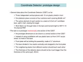
Coordinate Detector: prototype design • General idea about the Coordinate Detector (CDET) so far: • Three independent vertical planes with 15 cm plastic shield in front • One detector plane consists of four sections each covering 96x96 cm2 • The active element of each section is a stack of 0.5x3 cm2 scintillator bars, split in half, viewing the target • WLS fibers run through holes in the bars and transmit light to H8711-10 16-channel PMT • The task is to prototype mechanically one section of the CDET • the prototype dimensions to be close to a central section of the CDET • Instead of using scintillators will use plastic bars cut from 3/16” acrylic sheet; no holes in the bars • Front plate will be holding the assembly, made of ¼” aluminum • The bars divided in five stacks vertically and strapped to the front plate • The neighboring stacks from different section should touch each other • The thickness of the detector plane should not be much bigger than the thickness of the active part, 30mm
Connection between sections • An idea how to connect two sections without gaps between stacks • Two sections shown, each with five vertical stacks, split in half • Each stack is strapped to the front plate at different positions to make transition between the sections • The straps run through holes in the front plate • All approximate dimensions in inches
PMT to WLS connection PMT • Key element in the design, defines the thickness of one CDET section, light sealing, etc. • PMT is glued in a plastic PMT holder • PMT holder is firmly attached with screws to the front plate while the PMT goes through a hole sticking outside few mm • The WLS (not shown) are glued in the “cookie” inside holes • The cookie is attached to the front plate with springs • Aluminum plate (3mm) covers the back side of the detector • Dowel pins in the front plate center the positions of the PMT holder and the cookie • All dimensions in mm Side view WLS cookie PMT holder Front plate PMT holding plate Bottom view