Download
1 / 24
250 likes | 385 Views
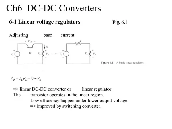
Custom DC-DC converters for distributing power in SLHC trackers. B.Allongue 1 , G.Blanchot 1 , S.Buso 2 , F.Faccio 1 , C.Fuentes 1,3 , P.Mattavelli 2 , S.Michelis 1,4 , S.Orlandi 1 , G.Spiazzi 2 1 CERN – PH-ESE 2 Dept. Information Engineering, Padova University, Italy

E N D
Custom DC-DC converters for distributing power in SLHC trackers B.Allongue1, G.Blanchot1, S.Buso2, F.Faccio1, C.Fuentes1,3, P.Mattavelli2, S.Michelis1,4, S.Orlandi1, G.Spiazzi2 1CERN – PH-ESE 2Dept. Information Engineering, Padova University, Italy 3UTFSM, Valparaiso, Chile 4EPFL, Lausanne
Outline • Power distribution in the trackers • In LHC trackers and projection to SLHC • DC-DC converters based solution • Power losses on cables • Main challenges in HEP experiments • Proposed power distribution scheme • Implementation • Different converter topologies • 1st stage • 2nd stage • Conclusions S.Michelis, CERN PH/ESE
Distributing power in LHC-SLHC PS Typical low-voltage power distribution in LHC trackers: No on-detector conversion. Low-voltage (2.5-5V) required by electronics provided directly from off-detector. Sense wire necessary for PS to provide correct voltage to electronics. Cables get thinner when approaching the collision point (strict material budget). Patch Panels (passive connectors) • In view of SLHC: • Scheme not easily scalable to the larger currents expected (see next slides) S.Michelis, CERN PH/ESE
What needs to be powered? (1) All ASICs will be manufactured in an advanced CMOS (or BiCMOS) process, 130nm generation or below. Here we consider only CMOS ASICs. Detector module • Front-End readout ASIC • Idigital≥ Ianalog (for instance, current projection for ATLAS Short Strip readout is Ianalog~ 20mA, Idigital ~ 60-100mA) • 2 power domains: Van=1.2V, Vdig=0.9-0.8V (as low as possible) • Clock gating might be used => switching load Detector • Hybrid/Module controller • Ensures communication (data, timing, trigger, possibly DCS) • Digital functions only • It might require I/Os at 2.5V Read-out hybrid Rod/stave Other than the rod/stave controller, optoelectronics components will also have to be used, requiring an additional power domain (2.5-3V) S.Michelis, CERN PH/ESE
What needs to be powered? (2) Large waste of power if Van=Vdig=1.2V Large current increase (Power on cables = RI2) • Summary • 3 Voltages to be provided to minimize power consumption: • 2.5V for optoelectronics and (maybe) control/communication ASICs • 1.2V for analog circuitry in FE ASICs • 0.8-0.9V for digital circuitry in FE ASICs. This domain uses most of the current! • Digital current might be switching in time (to really minimize the power) • Power and Current in LHC/SLHC • Projection based on current estimate for ATLAS upgrade • Only accounting barrel detector, power from Readout ASICs only • SCT is LHC ATLAS Silicon Tracker detector, to be replaced (grossly) by Short Strip layers in present upgrade layout (strawman design) S.Michelis, CERN PH/ESE
Outline • Power distribution in the trackers • In LHC trackers and projection to SLHC • DC-DC converters based solution • Power losses on cables • Main challenges in HEP experiments • Proposed power distribution scheme • Implementation • Different converter topologies • 1st stage • 2nd stage • Conclusions S.Michelis, CERN PH/ESE
Reduction of cables power losses Converter Ratio N V I N V I/N V2 I2 Converter 2 R Solution without converter: • Power losses on cable = Solution with converter: • Power losses on cable = S.Michelis, CERN PH/ESE
Custom converter for SLHC PS • The converters will be placed inside the tracker, therefore they will be embedded in • radiation (>100Mrd) • magnetic (2T-4T) fields • Commercial converters do not target this environment because they are not radiation tolerant and use ferromagnetic material that saturate at this external magnetic field. • It is therefore necessary to develop custom converters that meet the HEP requirements S.Michelis, CERN PH/ESE
Tolerance to experiment environment • Radiation tolerance the converter requires the use of a technology able to work up to at least 15-20V. This high voltage technology are typically tailored for automotive applications. More information on the talk during the power working group meeting. • Magnetic field tolerance We are obliged to use coreless (air-core) inductors because all the ferromagnetic material are not usable with an external magnetic field of 2-4T and at a switching frequency of 1Mhz S.Michelis, CERN PH/ESE
Outline • Power distribution in the trackers • In LHC trackers and projection to SLHC • DC-DC converters based solution • Power losses on cables • Main challenges in HEP experiments • Proposed power distribution scheme • Implementation • Different converter topologies • 1st stage • 2nd stage • Conclusions S.Michelis, CERN PH/ESE
Proposed power distribution scheme “analog bus” 2.5V 10V “digital bus” 1.8V 2.5V (I/O) 0.9V (core) 1.25V (Vana) 1.25V (Vana) 0.9V (Vdig) 0.9V (Vdig) Controller ASIC Readout ASICs • Conversion stage 1 (ratio 4-5.5) • Vin=10V => high-V technology • Same ASIC development for analog and digital, only feedback resistive bridge is different • Conversion stage 2 (ratio 2) • Embedded in controller or readout ASIC • Closely same converter for analog and digital (different current, hence different size of switching transistors): macros (IP blocks) in same technology S.Michelis, CERN PH/ESE
Implementation example 10V If Ihybrid<< Iout_converter If Ihybrid~ Iout_converter 2 Converter stage2 on-chip 2 Converter stage 2 on-chip 10V Detector Detector 2.5V 1.8V Detector 2.5V 1.8V Converter stage 1 2.5V Detector 1.8V 2.5V 1.8V 2.5V Optoelectronics 1.25V Stave controller Converter stage 1 on-hybrid 10V Converter stage 2 10V Converter stage 1 on-stave Rod/stave S.Michelis, CERN PH/ESE
Summarizing proposed scheme • Components needed: • ASIC for conversion stage 1 (10V in, hence “high-V” technology) • ASIC macro (IP) for conversion stage 2 (in the FE ASIC technology) • Air-core inductor(s) • SMD Capacitances • Features • Conversion ratio close to 10 allows for considerably decreasing power loss on cables • Only 1 power line (10V) from off-detector, all other voltages generated locally • Capability to power both analog and digital domains with required voltage to minimize power – even in the event of switching loads • Only inefficiency due to conversion losses • High modularity • On-chip conversion stage allows in principle each ASIC to be turned on/off independently (power groups can also be envisaged): • Controller ASICs can be turned on first and alone – easy start-up condition • Depending on the modularity, defective FE ASICs (or groups) can be turned off to prevent the rest of the hybrid to be affected S.Michelis, CERN PH/ESE
Outline • Power distribution in the trackers • In LHC trackers and projection to SLHC • DC-DC converters based solution • Power losses on cables • Main challenges in HEP experiments • Proposed power distribution scheme • Implementation • Different converter topologies • 1st stage • 2nd stage • Conclusions S.Michelis, CERN PH/ESE
Different converter topologies (1/3) The following DC/DC step down converter topologies have been evaluated and compared in view of our specific application. • Single phase synchronous buck converter • Simple, small number of passive components • Larger output ripple for same Cout • RMS current limitation for inductor are output capacitance • 4 phase interleaved synchronous buck converter • Complete cancellation of output ripple for a conversion ratio of 4 (with small Cout) • Smaller current in each inductor (compatible with available commercial inductors) • Large number of passive components • More complex control circuitry L1 Vin Vout Q1 Rload Q2 Cout L1 Vin Vout Q1 Q2 L2 Rload Cout Q3 Q4 L3 Q5 Q6 L4 Q7 Q8 S.Michelis, CERN PH/ESE
i g Q 1 i C r 1 Q I L 2 o r V g + D v C 1 r + r v Load C o 2 D 2 Different converter topologies (2/3) • Two phase interleaved synchronous buck converter with integral voltage divider • Complete cancellation of output ripple for a conversion ration of 4 (with small Cout) • Simpler control and smaller number of passive components than 4 phase interleaved • Multi-resonant buck converter • Very small switching losses (zero voltage and zero current switching) • To achieve resonance: • Current waveforms have high RMS value => large conductive losses => lower efficiency • Voltage waveforms have high peaks, possibly stressing the technology beyond max Vdd • Different loads require complete re-tuning of converter parameters S.Michelis, CERN PH/ESE
i g Q + 1 i C x 1 Q I 2 o + V v g x C Q x 3 + v Load C o 2 Q 4 Different converter topologies (3/3) • switched capacitor voltage divider • rather simple , limited number of passive components • lack of inductor => good for radiated noise and for compact design • No regulation of the output voltage, only integer division of the input voltage • Efficiency decreases with conversion ratio (larger number of switches) • Good solution for ratio = 2, for which high efficiency can be achieved S.Michelis, CERN PH/ESE
Conversion stage 1: topology Waveforms of the different topologies have been computed with Mathcad, and conversion losses have been estimated for each of them in the same conditions: Vin= 10V, Pout= 6W, Vout= 2.5V (step down ratio = 4), use of AMS 0.18um technology with approximate formula to account for switching losses The best compromise in terms of efficiency, number of components required, complexity and output ripple is the 2 phase interleaved buck with integrated voltage divider. S.Michelis, CERN PH/ESE
Implementation: conversion stage 1 • The final result of our study is that, for the development of a unique ASIC conversion stage 1 for both analog and digital power distribution, the best solution is: • 2-phase interleaved buck with integrated voltage divider • Switching frequency = 1 MHz • On-resistance of switching transistors = 30 mW • The inductor can be chosen for the specific output current wished in the application, achieving the efficiency estimated in the graphs below for the AMS 0.18 technology (Coilcraft RF 132 series inductors are used) DIGITAL, Vout=1.8V ANALOG, Vout=2.5V S.Michelis, CERN PH/ESE
Implementation: conversion stage 2 Vin Q1 Q2 Vout=Vin/2 Q3 Q4 gnd • Two converters to be embedded on each chip • Output current rather modest (20-200 mA) • Inductor-based converters not envisageable: • With on-chip inductors (high ESR) the efficiency would be extremely low • The use of several discrete inductors per ASIC is not desirable – already only for system integration purposes • Switched capacitor converters more suitable • Acting as voltage divider (÷2) • They unfortunately do not provide regulation, which must be relied on from conversion stage 1 • Achievable efficiency has been estimated, then refined with a quick simulation in a 130nm technology (use of I/O transistors) • Efficiency (Vin=1.8V, Vout=0.9V, Iload=166mA, f=20MHz) = 93% • It should be pointed out that no study on the optimization of this converter has been made – one only topology, with one fixed frequency has been studied (efficiency can be improved further by decreasing the frequency, for instance). S.Michelis, CERN PH/ESE
Efficiency of the two stages “analog bus” 2.5V, 4A 10V “digital bus” 1.8V,4A 2.5V (I/O) 0.9V (core) 1.25V (Vana) 1.25V (Vana) 0.9V (Vdig) 0.9V (Vdig) Controller ASIC Readout ASICs 90% 87% >93% >93% >93% >93% >93% Conversion stage 1 (ratio 4-5.5) Two phase buck interleaved with voltage divider Conversion stage 2 (ratio 2) switched capacitor voltage divider with ratio 2 • The efficiency of the two stages is equal to the multiplication of the efficiency of each stage: • Analog: 90%*93%=84% • Digital: 87%*93%=81% S.Michelis, CERN PH/ESE
Projection for total power • Projection to SLHC ATLAS SS tracker • Comparison of SCT (present ATLAS strip tracker) and Short Strip strawman design for SLHC • Power loss in cables only for last Patch-Panel – at the edge of the tracker, in the hypothesis of 1W resistance on the return path per cable • For DC-DC conversion, we assume 10V input voltage to the stave/rod S.Michelis, CERN PH/ESE
Conclusions Summary • We presented a DC-DC based power distribution architecture that: • Provides different on-module voltage level. This allows a minimization of the active power • local voltage regulation and capability of switching on/off independently each FE-chip or groups of FE-chips • reduction of on-cable power losses • DC-DC converter topologies are being selected: • Two phase interleaved with voltage divider or simple buck for the first stage • Switched capacitor with ratio 2 for the second stage Working plan • Radiation tolerance studies on different technologies • Design of a prototype of the converter with the selected topology for stage 1: • with discrete components • in the AMIS technology • Further studies on noise coupling will be carried out. S.Michelis, CERN PH/ESE
More information Other aspects very relevant for a successful implementation can be found on: • Noise • measurement Noise Susceptibility Measurements of F-E Electronics Systems (indico link) on the talk of G. Blanchot this afternoon at 15:55 • characterization Characterization of the noise properties of DC to DC converters (indico link) during the poster session • Progress on prototypes Progress on DC/DC Converters Prototypes (indico link) talk during the power working group • Radiation test results Radiation measurement on AMIS 0.35 technology (indico link) talk during the power working group • First prototype A prototype ASIC buck converter for LHC upgrades (indico link) during the poster session S.Michelis, CERN PH/ESE