Download

1 / 25
250 likes | 360 Views
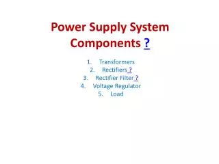
Radiation- and Magnet field- Tolerant Power Supply System. System Concept : Water-cooled Floating Power Supply Monitoring & remote control 19‘‘ Power Bin. Modular Floating Power Supply. 8-12 independent potential free outputs, floating Sensing of all outputs

E N D
Radiation- and Magnet field- TolerantPower Supply System System Concept :Water-cooled Floating Power Supply Monitoring & remote control 19‘‘ Power Bin
Modular Floating Power Supply • 8-12 independent potential free outputs, floating • Sensing of all outputs • DC output power 2,2kW at 250VDC per 3U box (depends on installed modules)
Modular Floating Power Supply • CE conform EN 50 081/82 part 1 • Safety in accordance with EN 60 950 • Water cooled • Easy insertion / extraction locking lever and carrying handle
Modular Floating Power Supply • Power box for 6 modules, single or dual output • Floating Range >10V (min. ca. 1,5 x Uout) • Up to 100mT Magnet field tolerant
Magnetic and Radiation Tolerant Power Module Adjustable Values on the Regulator Board : • Output Voltage • Current Limit • max. Module Voltage (OVP) manual trimming
Modular Control Board Basic Board with: • Clock Generation • Global Module Off if Mains Voltage too low • All Monitoring & Control Signals are fed to an (optional) plug-in monitoring board • (Already developed except the plug in board)
Monitor and Control Board (simple) • One analog output for each voltage & current (2 * 12 lines + return) • Inhibit input for each channel (12 lines + return) • Connection to external control via 50-wire flat cable(i. g. to EMLB) (available)
Monitoring Board (Medium Version) • Multiplexing of input / output signals (4 address lines, 1 enable line) • Voltage, Current, Temperature & Status (4 lines + return) • Inhibit input (1 line + return) • Connection to external control via 25-wire flat cable (Ready for board design)
Monitoring Board (Complex Version) • Redundant micro controller system • Measurement of Voltage, Current, Temperature & Status • Inhibit & Switch Off of each channel possible (this feature must be activated with a jumper) • Connection to external control via 2-wire CAN-Bus (Component evaluation and testing Stage)
Monitoring Board with ELMB integrated • connects all voltage, current, temperature and status signals to the CERN ELNB board • inhibit / switch off possible via ELNB outputs • Connection to external control via 2-wire ENLB can bus(possible solution, still to develop)
Available modules: • Range 2-7V <30A/200W Dual Output Module • Range 5-12V <20A/200W Dual Output Module • Range 2-7V <100A/500W Single Output Module • Range 5-10V <70A/500W Single Output Module • Voltage trimmable +/-20%, intern manually
CANbus & OPC serverworking with „Coplex Monitoring Board“ • Access to all monitoring information and control function • Can handle up to 126 Power Supplies with max. 8 channels 63 Power Supplies with more than 8 channels • One Address may use for “emergency” • Indicates each faulty detail
Canbus Interfacefor Crate Remote Control Wiener CANbus Interfaces can control and monitor • Power Supplies systems • voltages, currents, temperatures, failure reports Prepared by Institute of Nuclear Physics ; Cracow - POLAND
Canbus Interfacefor Crate Remote Control CANbus Controller • Conforms CAN specification 2.0A (11-bits identifier) • 9-pin male DSUB connector (CiA DS102-1 Specification) • Opto-isolated transceiver , unshielded cable can be used with at least 110 nodes for high speed (1 Mbaud) bus Prepared by Institute of Nuclear Physics ; Cracow - POLAND
Canbus Interfacefor Crate Remote Control Wiener CANbus Interface Protocol • COB ID mapping doesn’t directly correspond to the CAL/CMS priority definition • CANOpen protocol is not supported • No NMT, SDO, SYNC, TimeStamp, Nodeguard messages • It doesn’t conform Minimal Functionality Device Specification (CiA 301 profile) Prepared by Institute of Nuclear Physics ; Cracow - POLAND
CANbus Integration, Interface to SCADA PVSSII Application OPC Client I/F PVSSII Application OPC Client I/F via OPC standard CANbus Interface Commercial CanBus Interface PCI Cardwith Custom OPC Server CANBus Wiener Device Wiener Device Wiener Device Wiener Device Known devices only Prepared by Institute of Nuclear Physics ; Cracow - POLAND
Custom OPC Server • Features: • Supports only one type of devices (i.E. WIENER only) • Is dedicated to one type of PCI CAN I/F card (API library) – presently Kvaser Card • Needs to be redesigned if one of above changes Prepared by Institute of Nuclear Physics ; Cracow - POLAND
DCOM OPC Data Access Server Interfaces OPC Toolkit Process Data Access Functionality Configuration, Initialization KVASER PCI/CAN API calls Custom software CANbus KVASER PCI/CAN driver with Application Program Interface for C/C++ KVASER Firmware Custom OPC Server • Architecture: Prepared by Institute of Nuclear Physics ; Cracow - POLAND
Functional Blocks of the OPC Server Kit • Initializer of the driver and devices • Process data access queues handling • Two separate threads: listening and transmitting (for each CAN port) • Process data to/from CAN messages mapping • ERROR (and WARNING) messages logger Prepared by Institute of Nuclear Physics ; Cracow - POLAND
Network configuration example (variable namespace) Prepared by Institute of Nuclear Physics ; Cracow - POLAND
19”Power Bins for PL 500 / 6021High current outputs < 8 Channels
Connector sideof PL 500 / 6021Medium current outputs < 12 Channels