The ARM Register Set
190 likes | 1.11k Views
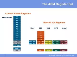
The ARM Register Set. Current Visible Registers. Current Visible Registers. Current Visible Registers. Current Visible Registers. Current Visible Registers. Current Visible Registers. r0. r0. r0. r0. r0. r0. r0. Abort Mode. SVC Mode. Undef Mode. FIQ Mode. User Mode. IRQ Mode.

The ARM Register Set
E N D
Presentation Transcript
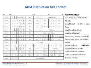
The ARM Register Set Current Visible Registers Current Visible Registers Current Visible Registers Current Visible Registers Current Visible Registers Current Visible Registers r0 r0 r0 r0 r0 r0 r0 Abort Mode SVC Mode Undef Mode FIQ Mode User Mode IRQ Mode r1 r1 r1 r1 r1 r1 r1 r2 r2 r2 r2 r2 r2 r2 Banked out Registers Banked out Registers Banked out Registers Banked out Registers Banked out Registers Banked out Registers r3 r3 r3 r3 r3 r3 r3 r4 r4 r4 r4 r4 r4 r4 r5 r5 r5 r5 r5 r5 r5 User User User User User FIQ FIQ FIQ FIQ FIQ FIQ IRQ IRQ IRQ IRQ IRQ IRQ SVC SVC SVC SVC SVC SVC Undef Undef Undef Undef Undef Undef Abort Abort Abort Abort Abort Abort r6 r6 r6 r6 r6 r6 r6 r7 r7 r7 r7 r7 r7 r7 r8 r8 r8 r8 r8 r8 r8 r8 r8 r8 r8 r8 r8 r8 r9 r9 r9 r9 r9 r9 r9 r9 r9 r9 r9 r9 r9 r9 r10 r10 r10 r10 r10 r10 r10 r10 r10 r10 r10 r10 r10 r10 r11 r11 r11 r11 r11 r11 r11 r11 r11 r11 r11 r11 r11 r11 r12 r12 r12 r12 r12 r12 r12 r12 r12 r12 r12 r12 r12 r12 r13 (sp) r13 (sp) r13 (sp) r13 (sp) r13 (sp) r13 (sp) r13 (sp) r13 (sp) r13 (sp) r13 (sp) r13 (sp) r13 (sp) r13 (sp) r13 (sp) r13 (sp) r13 (sp) r13 (sp) r13 (sp) r13 (sp) r13 (sp) r13 (sp) r13 (sp) r13 (sp) r13 (sp) r13 (sp) r13 (sp) r13 (sp) r13 (sp) r13 (sp) r13 (sp) r13 (sp) r13 (sp) r13 (sp) r13 (sp) r13 (sp) r13 (sp) r13 (sp) r13 (sp) r13 (sp) r13 (sp) r13 (sp) r13 (sp) r14 (lr) r14 (lr) r14 (lr) r14 (lr) r14 (lr) r14 (lr) r14 (lr) r14 (lr) r14 (lr) r14 (lr) r14 (lr) r14 (lr) r14 (lr) r14 (lr) r14 (lr) r14 (lr) r14 (lr) r14 (lr) r14 (lr) r14 (lr) r14 (lr) r14 (lr) r14 (lr) r14 (lr) r14 (lr) r14 (lr) r14 (lr) r14 (lr) r14 (lr) r14 (lr) r14 (lr) r14 (lr) r14 (lr) r14 (lr) r14 (lr) r14 (lr) r14 (lr) r14 (lr) r14 (lr) r14 (lr) r14 (lr) r14 (lr) r15 (pc) r15 (pc) r15 (pc) r15 (pc) r15 (pc) r15 (pc) r15 (pc) cpsr cpsr cpsr cpsr cpsr cpsr cpsr spsr spsr spsr spsr spsr spsr spsr spsr spsr spsr spsr spsr spsr spsr spsr spsr spsr spsr spsr spsr spsr spsr spsr spsr spsr spsr spsr spsr spsr spsr spsr spsr spsr spsr spsr
Register Organization Summary r0 r1 r2 r3 r4 r5 r6 r7 r8 r9 r10 r11 r12 r13 (sp) r14 (lr) r15 (pc) cpsr User FIQ IRQ SVC Undef Abort Usermoder0-r7,r15,andcpsr Usermoder0-r12,r15,andcpsr Usermoder0-r12,r15,andcpsr Usermoder0-r12,r15,andcpsr Usermoder0-r12,r15,andcpsr Thumb state Low registers r8 r9 Thumb state High registers r10 r11 r12 r13 (sp) r13 (sp) r13 (sp) r13 (sp) r13 (sp) r14 (lr) r14 (lr) r14 (lr) r14 (lr) r14 (lr) spsr spsr spsr spsr spsr Note: System mode uses the User mode register set
Condition code flags N =Negative result from ALU Z = Zero result from ALU C = ALU operation Carried out V = ALU operation oVerflowed Sticky Overflow flag - Q flag Architecture 5TE/J only Indicates if saturation has occurred J bit Architecture 5TEJ only J = 1: Processor in Jazelle state Interrupt Disable bits. I = 1: Disables the IRQ. F = 1: Disables the FIQ. T Bit Architecture xT only T = 0: Processor in ARM state T = 1: Processor in Thumb state Mode bits Specify the processor mode Program Status Registers 31 28 27 24 23 16 15 8 7 6 5 4 0 N Z C V Q I F T mode U n d e f i n e d J f s x c
Program Counter (r15) • When the processor is executing in ARM state: • All instructions are 32 bits wide • All instructions must be word aligned • Therefore the pc value is stored in bits [31:2] with bits [1:0] undefined (as instruction cannot be halfword or byte aligned). • When the processor is executing in Thumb state: • All instructions are 16 bits wide • All instructions must be halfword aligned • Therefore the pc value is stored in bits [31:1] with bit [0] undefined (as instruction cannot be byte aligned). • When the processor is executing in Jazelle state: • All instructions are 8 bits wide • Processor performs a word access to read 4 instructions at once