Download
1 / 15
150 likes | 276 Views
STUDYING THE OPTICAL PROPERTIES OF THE NPD MIRRORS. Yenny Martinez Brigham Young University March 20, 2002. ACKNOLEDGEMENTS. David Allred, R. Steven Turley, and Spencer Olson help and insight they give to me throughout the time of this resesarch

E N D
STUDYING THE OPTICAL PROPERTIES OF THE NPD MIRRORS Yenny Martinez Brigham Young University March 20, 2002
ACKNOLEDGEMENTS • David Allred, R. Steven Turley, and Spencer Olson • help and insight they give to me throughout the time of this resesarch • Matt Squires, Mike Newey, and many other students • assisting me in writing my thesis and finishing the research • Shannon Lunt and Elke Jackson • measurements taken via reflectometry
OUTLINE • Background Information: • Why study Mars? • Neutral Particle Detector (NPD) mirrors • Desired characteristics • Calculations made by us • Experimental Setup: • Making the NPD mirrors • Measuring the NPD mirrors • Conclusion
Riverbeds River canyons WHY STUDY MARS? BECAUSE MARS LACKS A MAGNETIC FIELD, ITS ATMOSPHERE HAS BEEN DEPLETED BY ITS INTERACTION WITH THE SOLAR WIND. WITHOUT AN ATMOSPHERE, ANY WATER PRESENT ON MARS MIGHT HAVE EVAPORATED AWAY AS WELL. • Photographs have been taken of Mars’ surface, revealing the existence of riverbeds and river cannons • Water might have been present! • Where did it go?
WHY STUDY MARS?(CONTINUED) • The European Space Agency is preparing a spacecraft for flight to Mars in 2003 • Its main instrument on board is the ASPERA-3, which holds a time-of-flight Neutral Particle Detector (NPD) • This NPD will measure the momentum of neutral particles in the solar wind that are postulated to be formed from the atmospheric particles. • Solar wind particles ionize the atmospheric gas • This ionized gas leaves the atmosphere along with the solar wind • By stripping electrons off neutral space atoms, the atmospheric atoms become neutral particles
START SURFACE TO STOP DETECTOR SCHEMATIC DIAGRAM OF NPD SENSOR -e -e TO START DETECTOR CHARGE PARTICLE DEFLECTION STOP SURFACE NEUTRAL PARTICLE DETECTOR (NPD) The NPD sensor is a one-dimensional pinhole camera with a 90° field of view • Charged particles are deflected, only allowing energetic neutral particles (ENAs) to enter • ENAs would release secondary electrons upon impact with the start surface • Secondary electrons start the time-of-flight detector • ENAs continue their path and hit a stop surface • Secondary electrons stop the time-of-flight detector
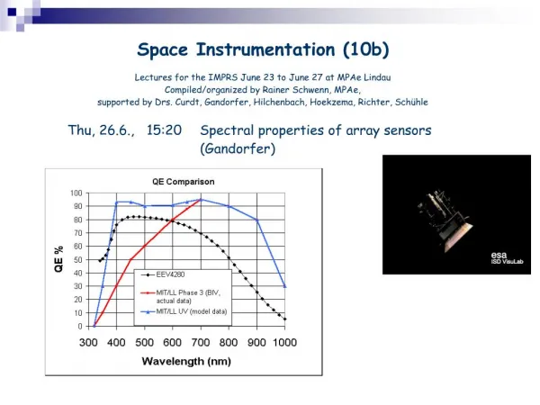
NEUTRAL PARTICLE DETECTOR (NPD)(CONTINUED) Desired characteristics for the NPD mirrors: • Surfaces must have ample electrons to emit when hit by the neutral particles • Surfaces must poorly reflect ultraviolet light (1216 Å) at the critical angle of 15°
NEUTRAL PARTICLE DETECTOR (NPD)(CONTINUED) • Work done by ESA affiliates showed that Cr, W, and their oxides would provide the necessary amount of secondary particles desired • A generic algorithm was used to determine suitable multilayer configurations using Cr, W, and MgF2 • For low reflective surfaces, a transmissive layer (MgF2) is needed between two reflective layers • The reflectance is determined by the thickness of the layers and the optical constants of the layers
NEUTRAL PARTICLE DETECTOR (NPD)(CONTINUED) OUR DESIGN: • Substrate • Ti based aircraft alloy • Supplied by the ESA • 275 Å Chromium • 103 Å Magnesium Fluoride • 8 Å Tungsten
EXPERIMENTAL SETUP • Creating the NPD mirrors • Evaporation • DC-Sputtering • Measuring their reflectivity • Variable angle reflectometer • Measuring their thickness • Ellipsometry • Monitored in the deposition using quartz crystal monitors
EXPERIMENTAL SETUP(CONTINUED) EVAPORATION: • Used to grow Cr and MgF2 layers DC-SPUTTERING: • Used to grow W layer
EXPERIMENTAL SETUP(CONTINUED) • Reflectivity measurements were made with a variable angle reflectrometer • Obtaining good measurements at low angles is difficult • A slight shift in angle drastically shifts the reflectivity • A misaligned system causes the same type of problems
EXPERIMENTAL SETUP(CONTINUED) • Ellipsometry was used to measure the thicknesses of the individual layers • Crystal monitors inside the evaporator dictate the relative thicknesses of the evaporation run
CONCLUSION • One of the automated runs on the actual flight mirrors • The 15° measurement is 24% reflectivity
CONCLUSION(CONTINUED) • Reflectance desired was 20% at 15° • Attained reflectances were 21%-24% • Possible reasons: • MgF2 and absorption of water • Smoothness • Other factors (measurements, time constraint,…) • Further study on NPD mirror simulations • Using SiO2 substrates instead of aircraft alloy • A very thorough study of surface and individual layer components