Math Co-Processor 8087
Math Co-Processor 8087. Gursharan Singh Tatla professorgstatla@gmail.com. Introduction. 8087 was the first math coprocessor for 16-bit processors designed by Intel. It was built to pair with 8086 and 8088 .


Math Co-Processor 8087
E N D
Presentation Transcript
Math Co-Processor 8087 www.eazynotes.com Gursharan Singh Tatla professorgstatla@gmail.com
Introduction • 8087 was the first math coprocessor for 16-bit processors designed by Intel. • It was built to pair with 8086 and 8088. • The purpose of 8087 was to speed up the computations involving floating point calculations. • Addition, subtraction, multiplication and division of simple numbers is not the coprocessor’s job. • It does all the calculations involving floating point numbers like scientific calculations and algebraic functions. www.eazynotes.com
Introduction • By having a coprocessor, which performs all the calculations, it can free up a lot of CPU’s time. • This would allow the CPU to focus all of its resources on the other functions it has to perform. • This increases the overall speed and performance of the entire system. • This coprocessor introduced about 60 new instructions available to the programmer. • All the mnemonics begin with “F” to differentiate them from the standard 8086 instructions. • For e.g.: in contrast to ADD/MUL, 8087 provide FADD/FMUL. www.eazynotes.com
Introduction • Math coprocessor is also called as: • Numeric Processor Extension (NPX) • Numeric Data Processor (NDP) • Floating Point Unit (FPU) www.eazynotes.com
Architecture of 8087 • 8087 coprocessor is designed to operate with 8086 microprocessor. • The microprocessor and coprocessor can execute their respective instructions simultaneously. • Microprocessor interprets and executes the normal instruction set and the coprocessor interprets and executes only the coprocessor instructions. • All the coprocessor instructions are ESC instructions, i.e. they start with “F”. www.eazynotes.com
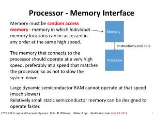
Architecture of 8087 www.eazynotes.com
Architecture of 8087 • The internal structure of 8087 coprocessor is divided into two major sections: • Control Unit (CU) • Numerical Execution Unit (NEU) www.eazynotes.com
Control Unit (CU) • It interfaces coprocessor to the microprocessor system bus. • It also synchronize the operation of the coprocessor and the microprocessor. • This unit has a Control Word, Status Word and Data Buffer. • If an instruction is ESC instruction, then coprocessor executes it. • If not, then microprocessor executes. www.eazynotes.com
Numeric Execution Unit (NEU) • This unit is responsible for executing all coprocessor instructions. • It has an 8 register stack that holds the operands for instructions and result of instructions. • The stack contains 8 registers that are 80-bits wide. • Numeric data is transferred inside the coprocessor in two parts: • 64-bit mantissa bus • 16-bit exponent bus www.eazynotes.com
Status Register www.eazynotes.com
Status Register • Status Register tells the overall status of 8087 coprocessor. • It is a 16-bit register. • It is accessed by executing the FSTSW instruction. • This instruction stores the contents of status register into memory. • Once the status is stored in memory, the bit positions of the status register can be examined. www.eazynotes.com
Status Register • Busy: It indicates that the coprocessor is busy executing the task. • Condition Codes (C0-C3): They indicate various conditions about the coprocessor. • Top of Stack: It indicates a register as top of stack register, out of the eight stack registers. • Exception Flag: It is set if any of the exception flag bits (SF, PR, UF, OF, ZD, DN, IO) are set. www.eazynotes.com
Status Register • Stack Fault: It is not available in 8087. It is active only in 80387 and above. • Precision: It indicates that the result has exceeded the selected precision. • Underflow: It tells if the result is too small to fit in a register. • Overflow: It tells if the result is too large to fit in a register. www.eazynotes.com
Status Register • Zero Divide: It indicates that you try to divide a non-zero value by zero. • Denormalized: It indicates that at least one of the operand is de-normalized. • Invalid Operation: It indicates an invalid operation. For e.g.: pushing more than eight items onto the stack, attempting to pop an item off an empty stack or taking the square root of a negative number. www.eazynotes.com
Control Register www.eazynotes.com
Control Register • Control Register controls the operating modes of 8087. • It is also a 16-bit register. • It performs rounding control and precision control. • It is also used to do masking and unmasking of the exception bits that correspond to the rightmost six bits of the status register. • FLDCW instruction is used to load the value into control register. www.eazynotes.com
Control Register • Rounding Control: It determines the type of rounding or truncating to be done. • Precision Control: It sets the precision of the result. • Exception Masks: It determines that whether an error effects the exception bits in the status register. • If it is one, then the corresponding error is ignored. • If it is zero and the corresponding error occurs, then it generates an interrupt, and the corresponding bit in status register is set. www.eazynotes.com
Tag Register Tag Values: 00 = Valid 01 = Zero 10 = Invalid 11 = Empty TAG 7 TAG 6 TAG 5 TAG 4 TAG 3 TAG 2 TAG 1 TAG 0 www.eazynotes.com
Tag Register • Tag Register is used to indicate the contents of each register in the stack. • There are total 8 tags (Tag 0 to Tag 7) in this register and each tag uses 2 bits to represent a value. • Therefore, it is a 16-bit register. Tag Values: 00 = Valid 01 = Zero 10 = Invalid 11 = Empty TAG 7 TAG 6 TAG 5 TAG 4 TAG 3 TAG 2 TAG 1 TAG 0 www.eazynotes.com
Pin Diagram of 8087 VCC GND AD14 AD15 AD13 A16/S3 AD12 A17/S4 AD11 A18/S5 AD10 A19/S6 AD9 BHE/S7 8087 RQ/GT1 AD8 INT AD7 www.eazynotes.com RQ/GT0 AD6 NC AD5 AD4 NC AD3 S2 AD2 S1 AD1 S0 AD0 QS0 NC QS1 NC BUSY READY CLK RESET GND
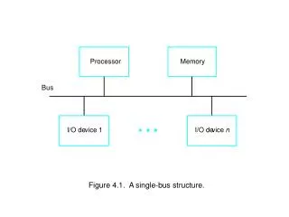
Interfacing of 8086 and 8087 • Multiplexed address-data bus lines are connected directly from 8086 to 8087. • The status lines and the queue status lines are connected directly from 8086 to 8087. • The Request/Grant (RQ/GT0 and RQ/GT1) signals of 8087 are connected to RQ/GT0 and RQ/GT1 of 8086. • BUSY signal of 8087 is connected to TEST pin of 8086. www.eazynotes.com
Thank You Have a Nice Day