Download
1 / 67
670 likes | 897 Views
Hybrid Texture Synthesis. Andrew Nealen Marc Alexa Discrete Geometric Modeling Group (DGM) Technische Universität Darmstadt Eurographics Symposium on Rendering 2003. Outline. Introduction. n x m Input Texture. N x M Output Texture.

E N D
Hybrid Texture Synthesis Andrew NealenMarc AlexaDiscrete Geometric Modeling Group (DGM)Technische Universität Darmstadt Eurographics Symposium on Rendering 2003
Introduction nxm Input Texture NxM Output Texture • The goal: Synthesize an output texture which isperceptually similarto the input texture. Also ensure that the result contains sufficient variation. 2D Texture Synthesis
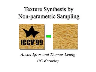
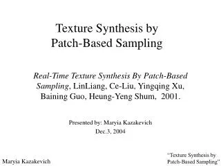
Introduction • Existing (and Impressive) Technology • Pixel-Based: • Non-parametric Sampling [Efros and Leung 1999] • Tree-structured Vector Quantization [Wei and Levoy 2000] • Image Analogies [Hertzmann et al. 2001] • Patch-Based: • Patch-Based Sampling [Guo et al. 2001] • Image Quilting [Efros and Freeman 2001]
Introduction Wei/Levoy Algorithm: Can occur when using structured Textures with rich histograms. This is due to the L2 norm. Possible Drawbacks ? • Loss of global structure • Loss of scale • Boundary mismatch • Blurring
Introduction Image Quilting Algorithm: boundary mismatch artifacts are noticeable Possible Drawbacks ? • Loss of global structure • Loss of scale • Boundary mismatch • Blurring
Introduction Patch-Based Sampling Algorithm: Can occur when texture features are not well-alignedacross patch boundaries Possible Drawbacks ? • Loss of global structure • Loss of scale • Boundary mismatch • Blurring
Hybrid Texture Synthesis • Combine best aspects from other approacheswhile avoiding (or improving over) known pitfalls: • Patch-based algorithms • Are good at preserving global structure • Can introduce artifacts along patch boundaries • Pixel-based algorithms • Preserve local coherence (MRF model: local and stationary) • Possibly fail to preserve global structure • This is especially problematic for textures with rich histograms and many high frequency features, due to the smoothing nature of the distance metric (L2norm)
Hybrid Texture Synthesis (HTS) • Hybrid, two-fold approach to texture synthesis • Adaptive patch sampling [Soler et al. 2002] • Start with a uniform quadrilateral grid of patches (the output) • Recursively split a patch if the best fit taken from the input texture is not good enough (a user-defined tradeoffmax) • Overlap re-synthesis(novel overlap repair strategy) • Mark invalid pixels in the overlap region • Validitymap is defined by the error surface E(x)=(xsrc – xdst)2 and a user-defined tolerance parametermax • Define an ordering for the invalid pixels and re-synthesize them using a per-pixel strategy
HybridSynthesizeAlgorithm 1: HYBRIDSYNTHESIZE(T,P,ov,Δmax,δmax,R) : R 2: for all patches pi ∈P do 3: [Pi,Δi]← FINDBESTPATCH(T,Ri−1, pi,ov) 4: if (Δi < Δmax or ISSINGLEPIXEL(pi)) then 5: Si ← ERRORSURFACE(Pi,Ri−1) 6: Pi ← MARKINVALIDPIXELS(Pi,Si,δmax) 7: Mi ← BUILDTRAVERSALMAP(Pi) 8: Ri,composite ← COMPOSE(Pi,Ri−1) 9: Ri ← OVERLAPRESYNTHESIS(T,Ri,composite,Mi) 10: else 11: Ps ← SPLITPATCH(pi) 12: ovs ←max(3, ov/2) 13: Ri ← HYBRIDSYNTHESIZE(T,Ps,ovs,Δmax,δmax,Ri−1) 14: end if 15: end for 16: return R
FindBestPatch(Algo.) 1: FINDBESTPATCH(T,Ri−1, pi,ov) : [Pi,Δi] 2: Ii, Ji ← BUILDIMAGEMASK(Ri−1, pi,ov) 3: Ei ← ERRORIMAGE(T, Ii, Ji) 4: Ei,trim ← TRIMINVALIDREGIONS(Ei, Ji, pi) 5: [Pi,Δi]← BESTPATCH(Ei,trim,T) 6: return [Pi,Δi]
In Search of Good PatchesSynthesizing a single patch Synthesize Black Patch i
In Search of Good PatchesExtracting the image mask • Grow patch by overlap (toroidally) Synthesize Black Patch i
In Search of Good PatchesExtracting the image mask • Extract image mask (Ii) and binary support (Ji), and circularly shift to upper left corner Synthesize Black Patch i Image Mask (Ii) Binary Support (Ji)
In Search of Good PatchesComputing the error image * Compute error Ei(x0) between Ii and T for each circular shift x0=(x,y) of the input texture T Input Texture (T) Image Mask (Ii) Binary Support (Ji)
In Search of Good PatchesComputing the error image C={R,G,B} (both with RGB color values in [0,1]) WR,G,B = {0.299,0.587,0.114} X0: circular shift of T Input Texture (T) Error Image(Ei) (1)
In Search of Good PatchesSelecting a Patch Input Texture (T) Error Image(E) Selected Patch (P) (2) • Given that Ji(x) Ii(x) = Ii(x),and the cross correlation between two images (functions) f ◇ g is defined as ( f ◇ g )(x0) = Σx f (x)g(x+x0) • The correlation f◇ g between two functions can be computed in O(N logN) • in fourier space as f ◇g = F-1(F( f )∗F(g)) • (N :number of pixels in the input texture) • In implementation it’s can be pre-compute the fourier transform for Tand need only recompute the fourier transforms of Iiand Jifor each new patch pi.
In Search of Good PatchesSelecting a Patch • Note: error image can be computed efficiently in the Fourier domain. Complexity: O(n log n)per patch. Input Texture (T) Error Image(E) Selected Patch (P)
Adaptive Patch SamplingPrinciple • Essentially: Hierarchical Pattern Mapping applied to the plane[Soler et al. 2002] Synthesize White Patch i > max Split Patch i < max
Adaptive Patch SamplingTrade-off • Trade-off between preserving global structure and avoiding detail artifacts max = 0.01 max = 1.0 max = 0.04
Adaptive Patch SamplingTrade-off • Trade-off between preserving global structure and avoiding detail artifacts max = 0.01 max = 1.0 max = 0.04
Adaptive Patch SamplingTrade-off • Trade-off between preserving global structure and avoiding detail artifacts max = 0.01 max = 1.0 max = 0.04
Overlap Re-synthesisOverlap error and pixel invalidation Patch and Image Mask Selected Patch (P)
Overlap Re-synthesisOverlap error and pixel invalidation Image Mask (I) Selected Patch (P)
Overlap Re-synthesisOverlap error and pixel invalidation Image Mask (I) Selected Patch (P) Error Surface (S)
Overlap Re-synthesisOverlap error and pixel invalidation • If(Ji(x) !=0 and Si(x)> δmax ) as invalid and in need of per-pixel re-synthesis. else if( Ji(x) != 0 and Si(x) < δmax ) are preserved and a stepwise alpha mask (feathering) is applied during Compositing. (Trade-off: user-defined maxis the pixel error tolerance. Setting to 1 results in pure feathering.) Patch and Image Mask P with Invalid Pixels (blue) Error Surface (S)
Overlap Re-synthesisCompositing P OVER Ri-1 Intermediate Result Patch with Invalid Pixels
Overlap Re-synthesisCompositing • Simple scanline re-synthesis: possibly insufficient causal neighborhood within valid pixelregion • Solution: alternative ordering (Pixel Traversal Map) Composited Result Patch with Invalid Pixels
Pixel Traversal-Map 1: BUILDTRAVERSALMAP(Pi) : Mi 2: level = 1 3: Dlevel ←binary image of size Pi initialized to 0 4: Dlevel ←set all valid pixels ∈ Pi to 1 5: Mi ←Dlevel 6: while (∃pixel ∈ Dlevel ∧ pixel = 0) do 7: level = level+1 8: Dlevel ← DILATE(Dlevel−1,Disk) 9: Mi ←Mi +(Dlevel ∧Dlevel−1) ∗level 10: end while 11: return Mi
Overlap Re-synthesisPixel Traversal Map (Ordering) • Pixel Traversal Map: repeated morphological dilation of the binary support for valid pixels with a euclidian disk of radius 1 (city-block distance transform). Composited Result Patch with Invalid Pixels Pixel Traversal Map (M)
Overlap Re-synthesisPixel Traversal Map (Ordering) • Pixel Traversal Map:step 1 Composited Result Patch with Invalid Pixels Pixel Traversal Map (M)
Overlap Re-synthesisPixel Traversal Map (Ordering) • Pixel Traversal Map: step 2 ... Composited Result Patch with Invalid Pixels Pixel Traversal Map (M)
Overlap Re-synthesisPixel Traversal Map (Ordering) • Pixel Traversal Map: ... step n Composited Result Patch with Invalid Pixels Pixel Traversal Map (M)
Overlap Re-synthesisPixel Traversal Map (Ordering) • Art Restorer Analogy: stepwise restoration of the hole from the boundary of the existing image. Composited Result Patch with Invalid Pixels Pixel Traversal Map (M)
Overlap Re-synthesisPer-Pixel Re-synthesis Synthesize red pixel from valid (or already re-synthesized) pixels Intermediate Result Pixel Traversal Map (M)
Overlap Re-synthesisPer-Pixel Re-synthesis Extract image mask (Ij) and binary support (Jj) for best-pixel search in the input texture. Complexity: O(n log n) per pixel. Image Mask (Ij) Binary Support (Jj) Intermediate Result
Overlap Re-synthesisPer-Pixel Re-synthesis Intermediate Result Pixel Traversal Map (M)
Overlap Re-synthesisPer-Pixel Re-synthesis Intermediate Result Shifted Pixel Traversal Map (M)
Overlap Re-synthesisPer-Pixel Re-synthesis Intermediate Result with Traversal Map Pixel Traversal Map (M)
Overlap Re-synthesisPer-Pixel Re-synthesis Overlap Re-synthesis Step 1 Pixel Traversal Map (M)
Overlap Re-synthesisPer-Pixel Re-synthesis Overlap Re-synthesis Step 2 Pixel Traversal Map (M)
Overlap Re-synthesisPer-Pixel Re-synthesis Overlap Re-synthesis Step 3 Pixel Traversal Map (M)
Overlap Re-synthesisPer-Pixel Re-synthesis Overlap Re-synthesis Result Pixel Traversal Map (M)
ResultsOverlap Repair Comparisons No Repair IQ PBS HTS
ResultsOverlap Repair Comparisons No Repair IQ PBS HTS
ResultsOverlap Repair Comparisons No Repair IQ PBS HTS
ResultsOverlap Repair Comparisons No Repair IQ PBS HTS
ResultsOverlap Repair Comparisons No Repair IQ PBS HTS
ResultsOverlap Repair Comparisons No Repair IQ PBS HTS
ResultsOverlap Repair Comparisons No Repair IQ PBS HTS