Control System Overview
An outline of design requirements, technical specifications, cost, and schedule baseline for the NSLS-II control system, including progress updates and staffing standards. Detailed control system requirements and design maturity for CD-3 approval.

Control System Overview
E N D
Presentation Transcript
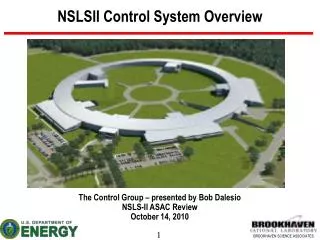
Control System Overview Bob Dalesio, Control Group Leader NSLS-II CD-3 DOE Review September 30 – October 2, 2008
Outline Design Requirements Technical Requirements & Specifications Cost & Schedule Baseline Design Maturity Requirements for CD-3 Approval Progress since CD-2 DOE Review Staffing Standards Technical Development Cost & Schedule Performance Construction Readiness Design Maturity Assessment Remaining Design Issues and Risks Conclusions
Control System Requirements – 1 of 2Preliminary requirements complete – detailed numbers in 2009 • Bunch Length 1-40 psecs • 2.6 usec ring revolution • Top off every 1 minute • Top off bunch train 140-300 nsec • Top off damping time 10-50 msecs (no extraction) • Manual control of orbit trims, quadrupoles, sextupoles, and insertion devices are asynchronous • ~10 Hz write/read is suitable for “turning knobs” for a power supply • 5 Hz updates to operators of up to 1000 chosen parameters • Archive up to 6000 parameters at a rate of 2 Hz continually • Must scale to support 150,000 physical I/O connections and 400,000 computed variables • 99.7% availability during operation
Control System Requirements – 2 of 2 • Transient Recording • Take coherent turn by turn orbit data for up to 800channels 1024 turns • Latch the last 10 seconds of data from all parameters in the storage ring • Beam line needs 1 msec archiving over 1 minute for temperatures and positions • Provide data for all control aspects • 5 KHz RF Feedback on beam phase • 10 kHz orbit feedback, (100 usec loop time) • 300 BPMs (10 per cell) • 2 * 120 Corrector PS in 30 I/O Controllers (IOC) • 20 msec equipment protection mitigation • 1 Hz model based control • 10 kHz power supply read backs triggered from timing sys • 10’s of Hz Data Collection for RF loop correction. • 80 psecs pulse to pulse timing jitter. • During top off, some beam lines will need 1.1 - 1.8 psecs of timing jitter • Provide electron detector as event for beam line
Cost & Schedule Baseline • Baseline • Manpower • 4 High Level Application Engineers • 2 RDB Architects • 8 Project Engineers • 1 EPICS Expert • 1 System Administrator • Hardware • 156 IOCs w/ timing hardware • $1M network hardware & 360K timing distribution • $400K Servers and Control Room Consoles • Software Licenses $300K • Schedule • Build synchronous distributed device controllers by end 2009 • Install Physics Environment for Application development 2009 • Install First release of component. lattice, and wiring RDB tools 2009 • Prototype subsystems and detailed design by end 2009 • Procure and implement subsystems in 2010 • Install and test Subsystems in 2011/2012 • Improve and manage RDB tools over the project to support design, installation, test, and maintenance. • Extend Physics Environment to support installation, test, commissioning and operation.
Design Maturity Requirements for CD-3 Approval Control System Design is 50% Complete
Progress Staffing Standards Developments
Staffing High Level Applications Nikolay Malitsky and Guobao Shen Two positions open to fill in early FY09: several likely candidates identified. Relational Database (IRMIS) Don Dohan and Gabriele Carcassi Contracts are being used to enhance our capabilities early in the project Project Engineers Yuke Tian 2 post docs starting early in FY09 on 2 year contracts 4 positions to fill in late FY09 and early FY10 Contract employees, sabbaticals, and purchase orders are being used to augment efforts. EPICS Tools and System Administration Position to be filled in the next 2 years Core software developer to be filled in the next 2 years
Control System Standards - 1 of 4 Nomenclature Standard is in place Psy:PI-Ssy:SI-Tsy:TI<Dev:DI>Sg:SgI-SD System Device Signal
Control System Standards - 2 of 4 Software standards are being evaluated • EPICS based • IRMIS tools used for all project configuration data: lattice, components, wiring etc. • Embedded Real-Time Operating System choices: RTEMS (LCLS, Spear, CLS) or VxWorks (APS, SNS, Diamond, SLS) • Linux Workstations running Debian • Use of standard EPICS engineering tools: Extensible Display Manager, Channel Archiver, Striptool, Alarm Handler • Evaluate the possibility of participating in the CSS development • Visual Database Configuration Tool w/ Modifications for Table Entry • Use of physics applications: Matlab Middle Layer Toolkit – MMLT (many light sources), eXtensible Accelerator Language - XAL (SNS/SLAC), Elegant (APS), Tracy online simulation (Diamond) • Evaluating Use of Beam Line Applications: SPEC, BluIce, IDL, SynApps (APS), GDA (Diamond)
Control System Standards - 3 of 4 Architecture for instrumentation is being prototyped Operator stations: Displays, Archiving, Alarm Management, Strip charts, Save/Restore Utility Events/ / Timing Data Shared Memory – Ethernet Hardware w/ Synchronous Protocol Ethernet – EPICS Channel Access Protocol Read Remote Ethernet and serial devices. High density IO, Motor Control Position Control CPU CPU CPU EVR CEL L EVR CEL L EVR CEL L MTRS EVG CEL L EVR CPU I /O CPU PS IOCs BPM IOCs PS IOCs Timing Master BPM Instrumentation Ethernet DCCT PS BPM PLC CNET I /O I /O ALS NET PrMon PS Fast Equipment Protection Signal BPM PS BPM PS BPM PS BPM ….. Non FOFB Diags. ….. Field I/O Field I/O Field I/O Field I/O PS BPM PLCS ,Slow I/O, High Reliability, Low Accuracy, High Density Vacuum, PPS, MPS, Non FOFB PS, Cryo., Facility control BPM
Control System Standards - 4 of 4 Hardware Components are being selected • Dell Linux development workstations • PLC Solutions Siemans Allen Bradley Control Logix • Building Automation ALS Needs fast Ethernet based interface board • VME crates Rittan 4 slot VME64x-2U4S-PS300C-SM 4,395.00 Rittan 7 slot VME64x-4U7S-PS900C-SM 5,510.00 Weiner 9 slot VME195xPO 6,050.00 Weiner 21 slot VME6023/611_JL 7,271.00 • CPU Boards Motorola MVME 5500 3,000.00 PP410 3,500.00 • Motor Controllers Hytec 8601 with motor driver 32 axis ~1,000/axis Newport XPS Intelligent motion controllers
Development Opportunities • Embedded Controllers need an open standard for high speed, deterministic functions. Work with other labs and board manufacturers to develop one. • High Level Applications currently tie together functions through data or file structures. To make the components of High Level Applications modular and distributed, a client/server architecture is needed. • Relational Databases support data management through the life of a project. Development of adequate tools to enter and report this data is required early.
Embedded Device Control – 1 of 3 Physics Applications: Correlation plots, orbit calculations, beam dump data Events/ / Timing Data – Beam Trip Event, Synch Data Event 2 GB Shared Memory – Communicates Cell Data @ 20 usecs Ethernet – EPICS Channel Access Protocol CPU CPU EVR CEL L EVR CEL L EVG CEL L CPU Compute Fast Orbit Feedback BPM IOCs PS IOCs Timing Master BPM PS Fast Equipment Protection Signal BPM PS BPM PS BPM PS BPM BPM
Embedded Device Control – 2 of 3 BPM Controller BPM Controller BPM Controller BPM Controller BPM Controller BPM Controller /OC EPICS RF Clock Distribution 45 MHz PCIx Interface +T0 + - Settling time on BPMs +0.0 µsecs - BPM to Compute Controller 512 bits = 64 bits * 8 BPMs 5.18 usecs = 518 bits over 100 MBit enet +6.5 µsecs - Compute Controllers to each other 15,360 bits = 30 nodes * 512 bits 15.4 usecs = 15,360 bits over 2 GB enet +21.9 µsecs – Compute local matrix 0 usecs + 21.9 µsecs - Communicate t Power Supply Controllers 256 bits = 4 PS * 64 bits each (v and h) 2.56 usecs +25.8 µsecs – loop complete settling time for magnets communicate diagnostic waveforms etc… +200 µsecs – start again Fiducial Distribution 1 Hz Prev Cell Core Controller I/OC EPICS PCIx Interface Core Controller PS Controller PS Controller PS Controller PS Controller I/OC EPICS PCIx Interface 100 MB ENET Next Cell Core Controller 2 GBit ENET
Embedded Device Control – 3 of 3 • FY 08 • Status: • Redundant 1.1 GByte Fibers transmitting • Master clock is distributed over grey wires in the test rig • 163 nsecs of latency to transmit through the board • Check character every 8 kb, no lost packets. • Carryover 60% of ‘08 money from late start • FY 09 • Cell Controller Development • Integrate and test communication core • Develop the interface from the cell controller to a processor • for integration into EPICS • Integrate external clock and fiducial • Device Controller Development • Develop the 100 Mbit interface on Cell Controllers • Test on device controller core with 100 MBit comm lines • Begin integration of these device controllers • Libera • Power supply control • LLRF control
High Level Applications – 1 of 4 Physics Applications (Thin Client) Physics Applications (Thick Client) Optics Resp.Matrix (S) Lattice Model Server Measured Orbit Orbit Differences Conversions Mid Level Data Client/Server Optics Deviations Name Mapping Gradient Errs & Corrections Application / Family Configuration Parameters Beam R. M. Diff’s Channel Access Data Server EPICS Client/Server Dipole Quad Sext. Corr. BPM RF Design Goal Computed Data Need to port Need to develop Distributed IOC Process Databases Under development Existing Designed lattice & installed hardware seq
High Level Applications – 2 of 4 High level Low level EPICS Client/Server EPICS Client/Server Distributed IOC process databases Tracy Simulation Engine Dipole Quad Sext. Corr. BPM RF Dipole Quad Sext. Corr. BPM RF Online simulation and physics tools are operational MMLT/AT XAL/Tracy Python/Tracy EPICS Client/Server EPICS Client/Server VIOC Real Machine
High Level Applications – 3 of 4 Kick beam: 1e-5 for 1st H&V Run setorbitgui (with 5 iterations) Orbit reset to 0 after correction • MMLT Setorbit – orbit correction (against VIOC)
High Level Applications – 4 of 4 • High Level Application environment is available in XAL, Matlab Middle Layer Toolkit and Python • An online simulation is running under the IOC in Tracy 3 • Libraries for HLA for online model will be done for AT and Tracy 3 • DDS open source data transport protocol installed and under evaluation • Direction • identify the client/server architecture that is required for orbit correction • Create the XML data grams that would be required for this application • Prototype the communication using DDS • Simulate the Servers that would be required for Orbit Correction • Evaluate alternative communication protocols: Extend Channel Access or Tine • Choose a protocol for the high level application environment (12 months) • Implement communication • Start to develop servers for physics applications
IRMIS – 1 of 3 Application Architecture Supports Independent Development 3rd party Java applications 3rd party Perl/Pyton scripts Integration with external tools (i.e. physcs) Few database utilities: backup, consistency check, etc… Web applications Client JavaScript bridge Applets and Widgets Java Client API XML protocol (REST style WS) Data Service layer Server Database layer
IRMIS- 2 of 3 Web Based Reports Editor Component Type Component Lattice EPICS Database Name Mapping Wiring Component Type Component Lattice EPICS Database Name Mapping Wiring Components Lattice EPICS Database Name Mapping Wiring Scripts Files for control Component Type Component Lattice EPICS Database Lattice EPICS Database Name Mapping Complete Complete FY 08 Complete FY 09
Design Maturity • Hardware standards are being evaluated for functionality, reliability, and cost for crates, processor boards, PLC family, and motion control. • Open Architecture Hardware standards are being developed to accomplish high speed, low latency applications such as fast orbit feedback, timing, and machine protection. Commercial solutions can provide some level of functionality if a fallback position is needed. We are working with manufacturers and in-house board developers to keep them appraised of the design and progress with the prototype. • Hardware for fast and high precision applications will be standardized as late as possible to take advantage of the latest hardware developments that can meet our requirements in the most cost effective manner. A good example of this is high speed digitizers for the ring current monitor – where the cost of good solutions have gone from $130K down to $30K and threaten to fall further. • Final design is scheduled to be done in 2009 as the detailed requirements for each of the subsystems are documented and the prototypes are developed and proven.
Design Maturity Requirements for CD-3 Approval Control System Design is 50% Complete All tools are developed in the EPICS community to provide all major engineering functions Real Time OS – does not affect any code. Software supported on RTEMS, vxWorks, Linux etc.. Hardware standards exist to meet all requirements Development being done provides alternate solutions that reduce cost and improve productivity Prototypes being developed in FY09 will be used to make the final design Detailed device lists developed in FY09 will be used to verify communications design and prepare for execution in FY09.
Design Maturity Requirements for CD-3 Approval Control System Design is 50% Complete
Remaining Design Issues Remaining design issues for construction start of Conventional Facilities: None. Other Remaining Design Issues: None.
Near Term Plans Prototype subsystem test stands for asynchronous applications Vacuum, facility control, machine protection, and personnel protection. Prototype subsystem test stands for synchronous applications Diagnostics, power supplies, and LLRF Develop first two physics application in a client/server architecture – orbit display and correction. Develop tools for lattice and wiring entry and browsing. Develop tools for exporting lattice to different platforms. Verify network design against all data requirements.
Concluding Remarks • Hardware standardization is being aggressively pursued with PLCs, processors, and crates being evaluated. (*) • All subsystems should be prototyped in FY09, early FY10 time frame. • We have critical mass to develop and prototype critical items in all areas of development and we continue to recruit and hire as budget authority permits (*). • Early Success in Staffing. Aggressive recruiting continues. To address this risk we are using aggressive recruiting and staff augmentation through the use of contract labor from companies and individuals with good EPICS experience. • Design Maturity is adequate for controls to assure delivery while taking advantage of the rapidly changing market. (*) Comments from the previous review that are being addressed. Also, coverage of wiring costs was confirmed.
EVMS – RF Controls (1 of 9) Controls is within its budet and performance parameters
EVMS – RF Controls (2 of 9) RF Subsystem Work Postponed to FY ‘09
EVMS Diagnostics Controls (3 of 9) Diagnostic Subsystem Postponed to FY ’09 – small bit of design done
EVMS EPS Control (4 of 9) EPS Subsystem Postponed to FY ’09 – no money to speak of
EVMS Control Room Costs (5 of 9) Control Room Postponed to FY ’11 – This was in the wrong year
EVMS Timing Control (6 of 9) Timing Subsystem Postponed to FY ’09 – small bit of design done
EVMS Operations Tools (7 of 9) IRMIS Development work is on track. The extra costs reflects 1.3.5.13 work done here….
EVMS High Level Applications (8 of 9) High Level Application Work – Great progress, costs went to 1.3.5.11
EVMS Control Management and Travel (9 of 9) Management and travel costs 10% underestimated. Some costs to subsystem in future
Backup – Subsystem Interface Design Power Supply Conventional Facilities Vacuum RF Beam Lines Diagnostics
Power Supply Interface Operator stations: Displays, Archiving, Alarm Management, Strip charts, Save/Restore Utility Events/ / Timing Data Shared Memory Ethernet – EPICS Channel Access Protocol PS IOC PS IOC 90 Storage Ring 4 Booster Ring 2 LINAC CEL L EVR CEL L CPU CEL L EVR CEL L CPU ………. MPS PLC MPS PLC PS PS PS PS PS PS PS PS PS PS PS PS PS PS PS PS PS PS PS PS PS PS PS PS Slow Correctors Slow Correctors Fast Correctors Fast Correctors
Conventional Facility Interface Operator stations: Displays, Archiving, Alarm Management, Strip charts, Save/Restore Utility Events/ / Timing Data Ethernet – EPICS Channel Access Protocol 5 1 per SR Equipment Building 1 for the injection Equipment Bldg. 1 for the cryo building EVR CPU Instrumentation Ethernet ALC NET ME-LGR Multi Equipment - LAN Gate Router. . ….. Field I/O Field I/O
Vacuum Interface Operator stations: Displays, Archiving, Alarm Management, Strip charts, Save/Restore Utility Events/ / Timing Data Ethernet – EPICS Channel Access Protocol 5 1 per SR Equipment Building 1 for the injection Equipment Bldg. 1 for the cryo building EVR CPU Instrumentation Ethernet 24 Port Digi PLC CNET I /O I /O Vacuum Device Controllers ….. Field I/O Field I/O
RF Interface Operator stations: Displays, Archiving, Alarm Management, Strip charts, Save/Restore Utility Events/ / Timing Data Shared Memory Ethernet – EPICS Channel Access Protocol RF IOC RF IOC 1 Storage Ring 1 Booster Ring 1 LINAC EVR CEL L CPU EVR CEL L CPU ………. HP PLCs HP PLCs Cav Cav Cav Cav LLRF LLRF 1 (up to 6) Storage Ring 1 Booster Ring 3 (or 4) LINAC
Beamline Interface Operator stations: Displays, Archiving, Alarm Management, Strip charts, Save/Restore Utility Events/ / Timing Data Shared Memory Ethernet – EPICS Channel Access Protocol BL IOC PS IOC 6 -1 per Beamline MTR EVR MTR CPU LVDT MTR EVR MTR CPU ………. LVDT MPS PLC MTR MPS PLC MTR
Diagnostics Interface – BPMs / Loss Mon. Operator stations: Displays, Archiving, Alarm Management, Strip charts, Save/Restore Utility Events/ / Timing Data Shared Memory Ethernet – EPICS Channel Access Protocol Diag IOC Diag IOC 30 Storage Ring 4 Booster Ring 2 LINAC EVR CEL L CPU ADC ADC EVR CEL L CPU ………. ADC - At only 5 locations Instrumentation Ethernet Instrumentation Ethernet BPM BPM 2 Loss Monitors 2 Loss Monitors BPM BPM Photon BPMs Photon BPMs BPM BPM BPM BPM BPM BPM BPM BPM BPM BPM Per ID Per ID BPM BPM