Control System Overview
480 likes | 517 Views
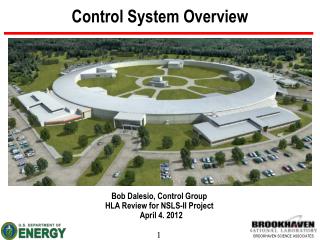
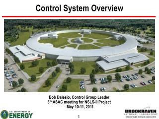
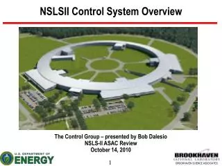
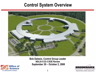
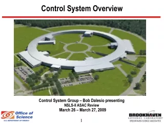
This presentation by Bob Dalesio at the NSLS-II ASAC Review in 2009 outlines the design and technical requirements, costs, staffing, standards, recent achievements, and future plans for the control system at NSLS-II. It covers specific control system requirements like bunch length, transient recording, RF and orbit feedback, equipment protection, timing resolutions, and staffing details. It also discusses cost and schedule baselines for hardware, software licenses, and manpower needed.

Control System Overview
E N D
Presentation Transcript
Control System Overview Control System Group – Bob Dalesio presenting NSLS-II ASAC Review March 26 – March 27, 2009
Outline Design Requirements Technical Requirements & Specifications Cost & Schedule Baseline Status Staffing Standards Technical Development Recent Accomplishments Near Term Plans Conclusions
Control System Requirements – 1 of 2 • Bunch Length 1-40 psecs • 2.6 usec ring revolution • Top off every 1 minute • Top off bunch train 140-300 nsec • Top off damping time 10-50 msecs (no extraction) • Slow control of orbit trims, quadrupoles, sextupoles, and insertion devices are slow but can be set synchronous to the orbit reference. • 5 Hz updates to operators of up to 1000 chosen parameters • Archive up to 20,000 parameters at a rate of 1 Hz continually • Must scale to support 150,000 physical I/O connections and 400,000 computed variables • 99.7% availability during operation
Control System Requirements – 2 of 2 • Transient Recording • Take coherent turn by turn orbit data for up to 800channels for 1024 turns • Latch the last 10 seconds of data from all parameters in the storage ring • Beam line needs 1 msec archiving over 1 minute for temperatures and positions • Provide data for all control aspects (no hidden parameters) • 5 KHz RF Feedback on beam phase • 10 kHz orbit feedback, (100 usec loop time) • 360 BPMs (12 per cell) • 120 Corrector PS (4 per cell) • All data available to system with revolution identifier for turn by turn data correlation. • 20 msec equipment protection mitigation • 1 Hz model based control • 10 kHz power supply read backs triggered from timing sys • 10’s of Hz Data Collection for RF loop correction. • 80 psecs pulse to pulse timing jitter. • During top off, some beam lines will need 1.1 - 1.8 psecs of timing jitter • 2 nsec timing resolution • Provide electron detector as event for beam line
Cost & Schedule Baseline • Baseline • Manpower by FY09 • 4 High Level Application Engineers • 2 RDB Architects • 9 Project Engineers • 1 EPICS Expert • 1 System Administrator • Hardware • 156 IOCs w/ timing hardware • $1M network hardware & 360K timing distribution • $400K Servers and Control Room Consoles • Software Licenses $300K • Schedule • Build synchronous distributed device controllers by end 2009 • Install Physics Environment for Application development 2009 • Install First release of component. lattice, and wiring RDB tools 2009 • Prototype subsystems and detailed design by end 2009 • Procure and implement subsystems in 2010 • Install and test Subsystems in 2011/2012 • Improve and manage RDB tools over the project to support design, installation, test, and maintenance. • Extend Physics Environment to support installation, test, commissioning and operation.
Staffing High Level Applications Nikolay Malitsky, Guobao Shen, and Jayesh Shah Contract work or new hire Relational Database (IRMIS) Don Dohan and Gabriele Carcassi Contracts are being used to enhance our capabilities early in the project Project Engineers Yuke Tian, TBD – power supplies Huijuan Xu – vacuum Rob Petkus - network Yong Hu, Kiman Ha – diagnostics Michael Davidsaver - RF David Dudley – facility and EPS control TBD – timing Daron Chabot, TBD – beam line control Contracts with other groups: Larry Doolittle et. al. LBL, Joe Meade BNL Contract employees for support (Sheng Peng, Steve Lewis, Steve Hunt, Cosylab, Observatory Sciences) EPICS Ralph Lange (BESSY), Mauro Gianchini (INFN) temporary for 12/6 months Position to fill
Control System Standards - 1 of 5 Nomenclature Standard is in place Psy:PI-Ssy:SI-Tsy:TI<Dev:DI>Sg:SgI-SD System Device Signal
Control System Standards 2 of 5 Archive Viewing Archive Analysis Program Interfaces C, C++, Fortran, JAVA IDL / Matlab / Mathematica ActiveX / DDE / VisBasic SDDS / SAD / tcl / PERL / Python State Notation Lang / FSQT User Tools DM/MEDM/DM2K/EDM/JDM Alarm Handler / stripTool/ knobManager Archive Access Archiving Channel Access Client (CAC) Connection Data Transfers Connection Server WAN/LAN/Local EPICS Tools Reduce Programming Connection Data Transfers Channel Access Server (CAS) Interfaces exist to add: drivers for new hardware state control model based control Configuration tools provide: data acquisition supervisory control steady state control operator displays alarm management DB Engine Types Device Support Driver Support I/O Controller
Control System Standards – 3 of 5 Software standards are being evaluated • IRMIS tools are used for all configuration data: lattice, components, wiring etc. • Embedded Real-Time Operating System choice: RTEMS (LCLS, Spear, CLS) or VxWorks (APS, SNS, Diamond, SLS) • Linux Workstations running Debian • Evaluate the possibility of participating in the CSS development • Visual Database Configuration Tool w/ Modifications for Table Entry • Use physics applications: Matlab Middle Layer Toolkit – MMLT (many light sources), eXtensible Accelerator Language - XAL (SNS/SLAC), Elegant (APS), Tracy online simulation (Diamond) • Evaluate Use of Experiment Control Tools: SPEC (ubiquitous), BluIce (SLAC), IDL, SynApps (APS/EPICS), GDA (Diamond), CBass (BNL), Scientific Studio
Control System Standards – 4 of 5 Architecture for instrumentation is being prototyped Operator stations: Displays, Archiving, Alarm Management, Strip charts, Save/Restore Utility Events/ / Timing Data Shared Memory – Ethernet Hardware w/ Synchronous Protocol Ethernet – EPICS Channel Access Protocol FOFB IOC Read Remote Ethernet and serial devices. High density IO, Motor Control Position Control CPU CPU EVR CEL L CEL L MTRS EVG CEL L EVR CPU I /O CPU PS IOCs Timing Master Instrumentation Ethernet DCCT RFBPM 1 FC1 PLC CNET I /O I /O ALS NET PrMon RFBPM 2 FC2 Fast Equipment Protection Signal FC3 RFBPM 8 SC1 XRay BPM1 SC2 ….. Non FOFB Diags. ….. Field I/O Field I/O Field I/O XRay BPM2 Field I/O PLCS ,Slow I/O, High Reliability, Low Accuracy, High Density Vacuum, PPS, MPS, Non FOFB PS, Cryo., Facility control SC6 XRay BPM4 Correctors
Control System Standards – 5 of 5 Hardware Components are being selected • Dell Linux development workstations • PLC Solutions – having pricing, checking reliability, prototyping test stands. Siemens Allen Bradley Control Logix • Building Automation ALS Needs fast Ethernet based interface board • VME crates Rittal 7 slot VME64x-4U7S-PS900C-SM 4,100.00 Weiner 9 slot VME195xPO 4,100.00 V-Ross uSystem uTCA w/MCH & Intel CPU 5,000.00 • CPU Boards Motorola MVME 3100 1,400.00 • Motor Controllers Oregon MicroSystems OMS MaxV 1,600.00
Development Opportunities • A Synchronous Device Interface that implements an open standard for high speed, deterministic functions provides a modular platform on which to develop a Fast Orbit Feedback system. • High Level Applications currently tie together functions through data or file structures. To make the components of High Level Applications modular and distributed (and therefore reusable), a client/server architecture is needed. • Implement asset management in the relational database. Development of adequate tools to enter, report, and track equipment and document its installation saves significant money over the life of the project.
Fast Feedback (3 of 4) Latency calculations:
Fast Feedback (4 of 4) SDI core design: LBL BNL: BPM measurement, GTP interface test, Integration • GTP interface test • fiber loop back two SFT ports • Data is internal counter
High Level Applications – 1 of 4 Physics Applications (Thin Client) Physics Applications (Thick Client) Optics Resp.Matrix (S) Lattice Model Server Measured Orbit Orbit Differences Conversions Mid Level Data Client/Server Optics Deviations Name Mapping Gradient Errs & Corrections Application / Family Configuration Parameters Beam R. M. Diff’s Channel Access Data Server EPICS Client/Server Dipole Quad Sext. Corr. BPM RF Design Goal Computed Data Need to port Need to develop Distributed IOC Process Databases Under development Existing Designed lattice & installed hardware seq
High Level Applications – 2 of 4 Online simulation and physics tools are operational MMLT XAL/Tracy Python/Tracy Elegant AT Tracy High level Low level EPICS Client/Server EPICS Client/Server EPICS Client/Server EPICS Client/Server EPICS Client/Server EPICS Client/Server Real Machine VIOC VIOC Model API Model API Distributed IOC process databases Elegant Simulation Engine Tracy Simulation Engine Dipole Quad Sext. Corr. BPM rf Dipole Quad Sext. Corr. BPM rf Dipole Quad Sext. Corr. BPM RF
High Level Applications – 3 of 4 Kick beam: 1e-5 for 1st H&V Run setorbitgui (with 5 iterations) Orbit reset to 0 after correction • MMLT Setorbit – orbit correction (against VIOC)
High Level Applications – 4 of 4 • High level application development environment is available for developing commissioning tools based on MMLT, XAL, or Python. • Online simulations of Tracy 3 and Elegant provide a solid EPICS environment for testing these tools. • The API for model servers is being formulated while these online simulations are brought online. • The DDS API is being prototyped as the interface for these applications. • Channel Access is being overloaded in version 3 and extended in version 4 to provide a client/server environment for these applications.
IRMIS – 1 of 4 Application Architecture Supports Independent Development 3rd party Java applications 3rd party Perl/Pyton scripts Integration with external tools (i.e. physcs) Few database utilities: backup, consistency check, etc… Web applications Client JavaScript bridge Applets and Widgets Java Client API XML protocol (REST style WS) Data Service layer Server Database layer
Database Status – 2 of 4 Web Based Reports Configuration Tools Component Type Component Lattice EPICS Database Name Mapping Wiring Component Type Component Lattice EPICS Database Name Mapping Wiring Component Type Component Lattice EPICS Database Name Mapping Wiring Develop Use Cases Scripts Files for control Component Type Component Lattice EPICS Database Name Mapping Wiring Lattice EPICS Database Name Mapping Complete Release 1 Complete FY 09 Complete FY 10 Tools develop in subsequent releases as users are added.
IRMIS 4 of 4 IRMIS ElegantDeck TracyDeck • Application prototype • Lattice Deck manager using IRMIS HLA App Deck Input Deck to IRMIS Object Mapping IRMIS Data Service Deck Parser Tracy/Elegant HLA App Deck Generator Other LatticeInformation IRMIS to Deck Object Mapping Tracy Elegant Simulation Server (Elegant) Simulation Server (Tracy)
Recent Accomplishments Prototype subsystems started for slow applications Vacuum, beam line and personnel protection. Prototype subsystems started for beam correlated applications Diagnostics, power supplies, and LLRF Prototype protocols running for High Level Applications architecture DDS deployed as an interface to some channel access mechanisms. Standard interface for orbit control running. IRMIS API for lattice entry and report is running and integrated into the online model environment. Preliminary design documents for vacuum, power supply, diagnostics, and network started. (*)
Near Term Plans Prototype subsystem test stands for facility control and personnel protection. Prototype subsystem test stands for diagnostics, timing and LLRF. Expand DDS interface to all channel access mechanisms. Prototype HLA communication requirements on CA V4 Prototype the Twiss Server. Develop tools for lattice and wiring for entry and browsing. Complete preliminary design documents for vacuum, power supply, diagnostics, and network (*). Write the preliminary design documents for timing, RF, PPS, and facility control (*).
Concluding Remarks • We have had good success in staffing. We are putting staff augmentation capability in place through the use of contract labor and temporary employees. • Choosing EPICS reduces the programming needed to accomplish the engineering control tasks. • The control team is developing the preliminary design documents and interface control documents for subsystems that have project engineers on board. The others will follow shortly(*) • Hardware tests will be in place for crates and processors in the next 2 months. (*) • All subsystems will be prototyped by early FY10. • Development in the relational database is keeping pace with the needs of the users of the relational database. • Development of the fast orbit feedback hardware now has reasonable momentum. A full working prototype based on the Avnet board should be operational in August. • The high level application environment already supports several models and sets of commissioning tools. The development of a client/server architecture is progressing well. (*) Comments from the previous review that are being addressed. Also, coverage of wiring costs was confirmed.
Backup – High Level Applications DDS open standard as an API for the high level applications client and server.
DDS-Based High Level Application Environment Conceptual Solution: Start the implementation of the DDS specification in the form of the EPICS extension based on the Channel Access protocol EPICS-DDS
Client/Server Architecture for High Level Apps High Level Application Environment – Matlab Middle Layer Toolkit, XAL Client API – CAV3: what is used now for channel data not enough TINE: is used for channel data – large interface DDS: superset of what is needed. Evaluate for packing/unpacking data CAV4: will be applied to the interface definition Protocol – CAV3: could overload array packet for early tests TINE: could also overload array packet for early tests Open-DDS: evaluated and deemed too slow – based on Corba ICE: evaluated and deemed to complicated to deploy CAV4: will be applied to the payloads we determine are needed for HLA Server API – CAV3: what is used now for channel data not enough TINE: is used for channel data – large interface DDS: superset of what is needed. Evaluate for packing/unpacking data CAV4: will be applied to the interface definition
Status Prototype / working solutions of the following aspects: http://sourceforge.net/projects/epics-dds • Middle-layer server [ caExampleApp ] • Application-specific fixed structures based on the EPICS waveform record, array of characters [ TwissApp ] • Synchronous access [ caExampleApp ] • Asynchronous access [ caMonitorApp ] • Benchmark use case [ caTime ]
Backup – Subsystem Interface Design Network Power Supply Conventional Facilities Vacuum RF Beam Lines Diagnostics
Subsystem I/F - Network AnyLAN Pre-tapped, redundant STAR topology • Pre-spliced = >$ material, <$ installation • On-site splicing = <$ material, >$installation • Little margin for error • (2) 60-fibre bundles in each direction = 120x2 • (1) tap/cell, (4) fibres/tap, Optitip -> LC harness • (2) spare fibres/cell = security, growth
Subsystem I/F – Fast Orbit Feedback Feedback Interface Operator stations: Displays, Archiving, Alarm Management, Strip charts, Save/Restore Utility Events/ / Timing Data Fast Orbit Feedback Synchronous Bus Ethernet – EPICS Channel Access Protocol FOFB IOC 30 Storage Ring 2 Injection CPU CEL L ………. RFBPM 1 FC1 RFBPM 2 FC2 DCPS 01 FC3 DCPS 02 RFBPM 8 SC1 XRay BPM1 DCPS 39 SC2 XRay BPM2 DC Power Supplies SC6 XRay BPM4 Correctors
Subsystem I/F – Conventional Facilities Operator stations: Displays, Archiving, Alarm Management, Strip charts, Save/Restore Utility Ethernet – EPICS Channel Access Protocol 5 1 per SR Equipment Building 1 for the injection Equipment Bldg. 1 for the cryo building CPU Instrumentation Ethernet ALC NET ME-LGR Multi Equipment - LAN Gate Router. . ….. Field I/O Field I/O
Subsystem I/F – Vacuum Operator stations: Displays, Archiving, Alarm Management, Strip charts, Save/Restore Utility Ethernet – EPICS Channel Access Protocol 5 1 per SR Equipment Building 1 for the injection Equipment Bldg. 1 for the cryo building CPU Instrumentation Ethernet 24 Port Digi 24 Port Digi Per Cell 30x PLC CNET I /O I /O Vacuum Device Controllers Vacuum Device Controllers ….. Field I/O Field I/O
Subsystem I/F - Vacuum Super period Vacuum - Even Cell
Subsystem I/F - Vacuum Super periodOdd Cell
Subsystem I/F - Vacuum • Injection device vacuum - Even Cell • Injection device vacuum - Odd Cell
Subsystem I/F - Vacuum • Beam line front end Vacuum • Note: • IP, TSP will be installed as a unit • NEG-C and NEG-S will be activated during maintenance period using portable power supply • RV will be operated manually and will not be monitored by control system
Subsystem I/F - RF Operator stations: Displays, Archiving, Alarm Management, Strip charts, Save/Restore Utility Events/ / Timing Data Phase Control Synchronous Bus Ethernet – EPICS Channel Access Protocol RF IOC 4 Storage Ring 1 Booster Ring 7 LINAC CPU CEL L ………. HP PLC CFC RFP CFC RFP DSP
Subsystem I/F – Beam line Operator stations: Displays, Archiving, Alarm Management, Strip charts, Save/Restore Utility Events/ / Timing Data Ethernet – EPICS Channel Access Protocol BL IOC PS IOC 6 -1 per Beamline MTR EVR MTR CPU LVDT MTR EVR MTR CPU ………. LVDT MPS PLC MTR MPS PLC MTR
Subsystem I/F – SR Diagnostics Operator stations: Displays, Archiving, Alarm Management, Strip charts, Save/Restore Utility Events/ / Timing Data Ethernet – EPICS Channel Access Protocol EVR CPU EVR F I R E CPU CPU FCT DCCT EVR BLM 00 Camera BLM 01 Camera BLM 02 Camera Camera BLM 59 Camera Camera
Subsystem I/F – SR Diagnostics Operator stations: Displays, Archiving, Alarm Management, Strip charts, Save/Restore Utility Events/ / Timing Data Ethernet – EPICS Channel Access Protocol EVR CPU EVR F I R E CPU CPU MTR MTR EVR TUNE Camera OSCILLATOR Camera
Design of Diagnostics Controls for Injector (Linac & LtB) Linac: LtB transport line : • IOCs for Linac & LtB diagnostics (2 in total) • One IOC (PCIe/Linux) for 3 WCMs + 2 FCTs • One IOC (microIOC/Linux) for 7 Screens via firewire & repeaters (longer distances than 4.5m)
Design of Diagnostics Controls for Injector (Booster & BtS) Booster: BtS transport line : • IOCs for Booster & BtS diagnostics (3 in total) • One IOC (PCIe/Linux) for 1 DCCT + 2 FCTs • One IOC (microIOC/Linux) for 12 Fluorescent screens via firewire & repeaters • One IOC (PC/Linux) for 29 BPMs in injector