Download

1 / 26
260 likes | 285 Views
This study explores the development of conduction-cooled coil technology using MgB2 and Nb3Sn for MRI systems, focusing on conductor specifications, coil design, and experimental results. The MgB2 coil was tested and exhibited good performance, transitioning by quench without a resistive baseline. Nb3Sn coil simulations and physical parameters were also analyzed.

E N D
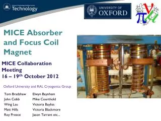
Demonstration of Conduction Cooled MgB2 and Nb3Sn Coil Segments for Magnet Applications Hyun Sung Kim, Chris Kovacs, Milan Majoros, Mike Sumption, E.W. Collings Center for Superconducting and Magnetic Materials, MSE, The Ohio State University J.Yue, D. Doll, X. Peng, M.Rindfleisch, Mike Tomsic Hyper Tech Research Funded by a National Institute of Biomedical Imaging and Bioengineering grant R01 grant, R01EB018363, and also an NIH bridge grant
Motivation • MRI systems based on MgB2are of significant interest as one way to develop liquid-cryogen-free MRI systems • MgB2’s Tc of 39 K invites conduction cooling, and lower cost makes it an economically viable • The low-Tc-like coherence length allows for persistent joints • Intermediate Tc helpfully increases the minimum quench energy while not suppressing the normal zone velocity too much • Conductor performance is at the level needed for MRI application, and conductor designs appropriate for MRIs can be made -- the need is for developing conduction cooled coil technology
Outline • Conductor/Coil specification • Instrumentation • Facility and Cool down • Ic measurement vs T • Discussion and Conclusions • If Time • Nb3Sn Coil work • Initial Persistent joint development
Conductor • Name 3364 • In-situ • 36 filament • Nb barriers • Cu interfilamentay matrix • Monel outer matrix • SMI-2% C doped • S-glass insulated • Reacted at 675/90 min under Ar Optical Micrograph of MgB2 conductor cross section, shown at wire OD = 0.84 mm.
Coil Design Specifics Coil material Former : 101 OFE copper All fasteners : 316 stainless steel Lead Insulator : Garolite G-10 or ceramic standoff Lead connector : Alloy 101 OFE Copper Coil Parameters Winding pack OD : 482.2 mm Winding Pack ID : 457.2 mm (18”) Winding Pack Height : 19.685 mm (0.775”) WP cross sectional area : 246.06 mm2 No. Turns : 225 Total Conductor L 328.8 m (1078.7’) Turns/layer : 19 (approx.) No. Layers : 12 Final coil preparation Solder for leads : Pb-Sn (40/60) Epoxy CTD Resistance measurements (after winding, after epoxy)
FEM Simulation Ic(B) curve of a typical strand with the calculated load line of the coil Magnetic field map at the coil critical current.
Experimental Set up • (2) Two stage GM cryocoolers • (2) Cold heads attached to the copper ring • Copper ring and coil are thermally connected with high purity copper strips • 4 BSCCO leads for each current tap MgB2 Coil Copper Ring Copper Strips • Heater attached in the copper ring to control the temperature of coil • Data acquisition system: Nanovoltmeters (Keithley), Thermometers (Lakeshore), Data acquisition (Labview)
Voltage Taps Critical Current Measurement: I-V measurement
Cooldown Voltage signals Temperature signals
I – V curves: 20 K, 0.1 A/s A bit of coil heating
I – V curves: 20 K, 2A/s Less coil heating
I – V curves: 20 K, 5A/s Very little coil heating
Ic vs T • A key aspect -- to test the end transitions, thus no preferentially cooling • Thus some current tap heating at lower T (where I higher) and for slower ramps. • However, we could observe that the coil, as well as the current in and out junctions, were good. • The coil transitioned by quench, and no resistive baseline was seen.
Summary • An MgB2-based react and wind coil was made and tested as part of a technology development effort for MgB2-based, cryogen-free, MRI. • A 36 filament MgB2 conductor was used to wind a small MRI-segment-like coil using a react and wind protocol. The coil was 457 mm ID and used a total length of conductor of 330 m. • The coil was then epoxy impregnated, instrumented, and tested. After initial cool down the coil Ic was measured as a function of temperature. • Both the coil itself and the terminations were seen to perform well -- A load line was generated – full analysis awaits 15 K measurement of this particular strand. • The coil transitioned by quench, and no resistive baseline was seen. A coil Ic of 200 A was seen at 15 K.
Nb3Sn FEM Simulation_Magnetic Ic(B) curve of the strand measured at 4.2 K with the calculated load line of the coil Magnetic field map at the coil critical current. Physical parameters of the coil at 4.2 K
Nb3Sn FEM Simulation_Temp, Strain. Coil temperature distribution. No current in the coil. Maximum temperature in the winding = 4.2209 K. Volumetric strain distribution in the winding cross-section.
Other Coil Measurements – Future Reporting Nb3Sn Coil MgB2 Coil
Swinging door cover to block shine but allow current leads to be pulled through Radiation shield for feedthrough (4) New 1.7 M cryostat to be in place this fall! Through-bolts; should be tapped holes 8 in port for instrumentation Feedthroughs. About 8 – 18pin connectors will fit on one port and there’s 4 of these. 3 inch clearance w/o MLI
Development of Persistent Joints • Two styles of joints • Superconducting solder type • Direct MgB2-MgB2 • In both cases, used already reacted wire • Preliminary testing to date using direct I-V, R < 10-10 • Decay Testing rig and samples in preparation for increased R sensitivity and decay test Working now to improve performance and measure to high sensitivity Superconducting Solder Type 4 K MgB2-MgB2Type 4 K
Moving from screening test to decay test • While further improvement in critical current of joints is still in process, it is important to measure R at values below 10-10 ohm • Thus, a decay rig was needed, as well as some initial testing and verification
New test arrangement for decay measurements – machine drawing
Test rig for decay measurements – with test NbTi joint mounted
Expansion of decay region NbTi test joint Results for a NbTi persistent joint (at the time of stage III, IV in overview result). Superconducting solder type.
Test of first persistent decay MgB2 sample Results for a MgB2 persistent joint (at the time of step III IV along the lines of NbTi overview figure). Superconducting solder type.
Conclusions (II) • Various MgB2 and Nb3Sn coil segments are being tested by conduction cooling For joints • Initial screening results show good results R < 10-10 ohm, indicate that it is time to move to decay measurements • The design of a new PJ decay rig is shown • Initial tests with NbTi and MgB2 joints are shown, and the results where described • Joint Testing and development (HTR-OSU) is in full swing, moving now to larger conductor joints for image guided system