Download
1 / 23
250 likes | 402 Views
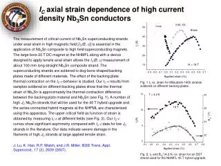
Development of High Current Nb 3 Sn Rutherford Cables for NED and LARP. D.R. Dietderich, A. Godeke, N.L. Liggins, and H.C. Higley WAMSDO, May 2008. Outline. Rutherford cables Cabling objective: Damage free strand Mechanically stable for winding a magnet Review cabling history for LBNL

E N D
Development of High Current Nb3Sn Rutherford Cables for NED and LARP D.R. Dietderich, A. Godeke, N.L. Liggins, and H.C. Higley WAMSDO, May 2008 D.R. Dietderich, LBNL
Outline • Rutherford cables • Cabling objective: • Damage free strand • Mechanically stable for winding a magnet • Review cabling history for LBNL • Dipole D-20 (13.5/14.5T) • Recent rectangular cable fabrication for LBNL magnets • RD-3 series (14.7 T) • HD-1 series (16 T) • Cables for LARP Technology Quadrupoles (TQ) • Proto-type cables for Next European Dipole (NED) D.R. Dietderich, LBNL
60 Strand Machine for Fabricating Rutherford Cables D.R. Dietderich, LBNL
Typical Rutherford Cable Cable 961 Edge deformations are important D.R. Dietderich, LBNL
Bad Good Good and bad cable edge deformation Main difference is different width of the cable D.R. Dietderich, LBNL
w Bad t Good Managing edge deformation Decoupling of Thickness & Width as opposed to Packing Factor Problem with Packing Factor Two Cables have equal area but are NOT the same 2 Cables: Same compaction or Packing Factor Design for this strand configuration at edge of cable NOT this strand Configuration 17.4 mm x 1.400 mm = 24.4 mm2 0.8 mm strand diameter 40 Strand cable Cable Area = 24.40 mm2 87% Packing Factor 17.0 mm x 1.435 mm = 24.4 mm2 0.4 is mm half a strand diameter This difference can be fatal D.R. Dietderich, LBNL
Deformation Parameters t and w • Thickness deformation t (~strain)t = (cable thickness/2x strand diameter) -1 • Width deformation w (~strain)w = (cable width – theoretical width)/(th. width)Theoretical width = PA = Cable pitch angle (factor 0.72 d not included in plots in this presentation) D.R. Dietderich, LBNL
Rutherford Cable Parameter Space No strand deformation at (0,0) Cable wider w larger 2 wire diameters (t=0) Cable thinner t more negative Theoretical width (w=0) D.R. Dietderich, LBNL
Rect. D-20 RD-3 HD-1 Key. D-20 Abandoned NbTi LHC-HGQ Parameter space cables for D-20, RD-3, and HD-1 D-20 is Cosine Theta Dipole (14.7T), RD-3 is Racetrack Dipole, and HD-1 is High Field Dipole (16T) D-20 RD-3 LBL Cable # 523 MJR-TWCA LBL Cable # 805R Oxford-ORe Keystoned D20 cables had ~20% loss in Ic and were more sensitive to transverse stress LBL Cable # 522 IGC-Int. Tin D.R. Dietderich, LBNL
Zones of interest from cables for D-20, RD-3, and HD-1 D-20 is Cosine Theta Dipole (14.7T), RD-3 is Racetrack Dipole, and HD-1 is High Field Dipole (16T) D-20 RD-3 RD-3 HD-1 Rect. D-20 Mechanically Unstable Good Zone LBL Cable # 523 MJR-TWCA Key. D-20 Abandoned ? LBL Cable # 805R Oxford-ORe Damaged Zone LBL Cable # 522 IGC-Int. Tin D.R. Dietderich, LBNL
Spec Made Technology Quad (TQ) – Cable Specifications & Production D.R. Dietderich, LBNL
Rect. D-20 RD-3 HD-1 Key. D-20 Abandoned Keystoned D-20 Cables NbTi LHC-HGQ TQ cable compared to past cables TQ D.R. Dietderich, LBNL
Facet size as online probe Bad • Facet length (x) should be less than Pitch Length/strand (y) • Minor axis Good D.R. Dietderich, LBNL
Thin edge of cables as online probe SEM Images of Cross Section Facets at cable edge 939R Facets > Pitch length/strand Bad 946R Good Facets < Pitch length/strand D.R. Dietderich, LBNL
GOOD BAD TQ cable widths after re-rolling Re-rolling after anneal is used to provide final shape • Do NOT re-roll cable to a smaller width • Fabrication (first rolling) • Anneal cable 200C for 4-6 h • Re-roll (second rolling) – final cable Spec. After cable 940R the processing was changed From one set of rolls To 2 sets of rolls, One for the fabrication and one for re-rolling ~ 50 micrometer wider Process improvement D.R. Dietderich, LBNL
Summary of Critical and Stability Currents for TQ Cables • All cables but 939R: • Reduced Jc(12T,4.2K) by about 0-3% • Reduced stability current (Is) by ~10% • Cable 939R (bad example with sheared sub-elements): • Reduced Jc (12T,4.2K) by about ~5% (Only) • Reduced stability current (Is) by ~50% (RRR loss?) • Concern – Past Jc measurements on cables with edge damage has shown them to be more sensitive to transverse stress. D.R. Dietderich, LBNL
NED Cable Parameters • LBNL Cable-CALC • Should increase the width from 26 mm to 26.9 mm. • Note: Removal of 1 strand is only 2.5% Ic reductionbut provides significantly more width margin D.R. Dietderich, LBNL
NED Cable Prototype Fabrication • LBNL cabling machine was pushed to its limits due to the: • Large strand diameter • High stiffness of the strand • Higher tension on the strands should make the cabling process easier. • It should permit fabrication of cables with a lower pitch angle (~16o) • Plus reduce the gaps between strands D.R. Dietderich, LBNL
NED cable edge facet summaryFour short prototype cable sections made • Facet/Pitch on the minor edge are similar • Section C has the smallest ratio • Section C has 4-8% Ic reduction (T. Boutboul, EUCAS-07 ) D.R. Dietderich, LBNL
Spec NED Prototype NED spec and prototype D.R. Dietderich, LBNL
Strand deformation inside a cable • Dimples at strand cross over points (box) • Deformation not uniform along a strand • Making cables thinner has shown no significant impact on performance • Perhaps cables can be made thinner • Strand deformation as it goes from the top of cable to bottom (oval) • Limits cable performance • Need 3D modeling to understand strand deformation at the cable edge Cable 784R D.R. Dietderich, LBNL
Modeling 2D and 3D 3D Modeling of Strand 2D Strand Modeling • S. Farinon, Presented at CHATS-AS 2006 Marco La China D.R. Dietderich, LBNL
Summary • The facet size on the edge of the cable provides a direct measure of the amount of strand deformation. • Indicates the amount of sub-element distortion inside the strand. • This work shows that a nearlydamage-free mechanically-stable cable can be produced from: • MJR and RRP strands with reduction of only 0-3% Jc (12T,4.2K). • PIT strand with reduction of 4-8% Jc (12, 4.2K) • Cabling damage (i.e. sheared sub-elements) had minimal effect on Jc but it has a significant impact on strand stability. • The stability current (Is) drops by ~50% in a strand with only a ~5% drop in Jc at 12T and 4.2K D.R. Dietderich, LBNL