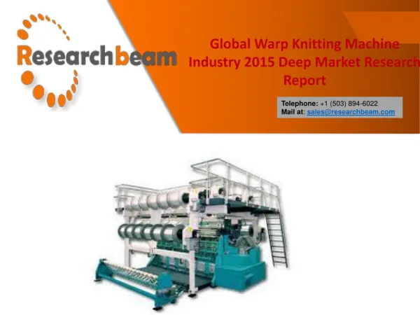
Warp Knitting Basics
Warp Knitting Basics. March 26,2010. Weft Warp. Warp Knits--the possibilities. Needle Technology. Until relatively recently warp knitting machines used four types of needle: The bearded needle The latch needle The compound needle The carbine needle

Warp Knitting Basics
E N D
Presentation Transcript
Warp KnittingBasics March 26,2010
Needle Technology • Until relatively recently warp knitting machines used four types of needle: • The bearded needle • The latch needle • The compound needle • The carbine needle • Bearded and compound needles were used on tricot machines, the latch needle on raschel and crochet machines and the carbine needle on crochet machines.
Knitting Technology • Recently the bearded needle has been dropped and development has focused on the compound needle due to its greater rigidity and ability to withstand higher yarn lapping forces (see Loop formation) than the bearded or latch needle.
Knitting Technology • Furthermore at the highest speeds (above 2,500 cycles/minute) the issue of latch impact on the hook starts to become a problem with latch needles. • In contrast the compound needle can be closed gently in a controlled manner even at the highest knitting speeds.
Warp Knitting Technology • Warp knitting machines--needles are mounted collectively and rigidly in a horizontal metal bar (the needle bar that runs the full knitting width of the machine). • Equally the yarn guides are also set rigidly into a horizontal metal bar (the guide bar that runs the full width of the machine).
Knitting Element Displacements • The diagram summarizes the somewhat confusing displacements made by the guide bar. The front of the machine lies to the right of the diagram.
Knitting Element Displacements • The diagram shows the individual yarn guides set in a solid bar. The front-to-back movements are called swings. The first swing from front to back is followed by a lateral shog: the overlap, which wraps the yarn in the needle hook.
Knitting Element Displacements • The next movement is a swing from back to front followed by the underlap that may be from 0 to 8 needle spaces depending on the fabric structure being knitted.
Tricot Knitting • In diagram (1.3 a & b) the guide bar swings from the front of the machine (on the right hand side of the diagram) to the back of the machine taking the yarn through the gap between two adjacent needles.
Tricot Knitting • Diagram (1.4 c) shows the guide bar moving laterally towards the observer. This is known as a shog movement, specifically the overlap that wraps the yarn around thebeard of the needle. • Diagram (1.4 d) shows the second swing in the cycle taking the yarn between adjacent needles back to the front of the machine. At this time the needle bar moves upwards to place the overlap below the open beard on the shank of the needle.
Tricot Knitting • Diagram (1.5 e) shows the presser bar moving forward to close all the needles and in (1.5 f) the closed needle passes down through the old loop and the sinkers move backwards to release the old loops so that knock-over can take place.
Tricot Knitting • In figure (1.6 g) the sinker bar moves forward to secure the fabric prior to the needle rising in the next cycle and at this stage the guide bar makes a second shog, this time an overlap which may be of 0 to 8 needle spaces depending on the structure being knitted.
Tricot Knitting • The machine type in this series of diagrams is a tricot machine and on this type of machine there is no continuous knock-over surface. • The belly' of the sinker provides support to the fabric by preventing the underlaps from moving downwards. • For this reason it is not a good idea to knit fabrics with few underlaps such as net or lace on a tricot machine. • They are much better knitted on a Raschel machine with a continuous knock-over trick plate.
Tricot Knitting • The diagrams you are about to see illustrate a tricot machine with compound needles. • The sequence of events is almost exactly the same as for the bearded needle with the exception that the overlap lays the yarn into the open hook and not onto the beard, and the compound needle is closed by relative displacement between the needle and the closing element.
Guide Bar Shog, Overlap and Underlap • The displacements shown for the needle, sliding latch, guide bar swing and sinker bar are the same irrespective of the type of fabric being produced by the machine.
Guide Bar Shog, Overlap and Underlap • The shog movements determine the type of fabric produced and they need to be changed each time the fabric structure is modified. • Crucially the shog movements must place the guides at the centre of the gap between adjacent needles with 100% accuracy every knitting cycle for the entire lifetime of the machine. • If there was a failure in the shog displacement and the needle bar moved by less than a full needle pitch then in all likelihood the yarn guides would collide with the needles during the swing movement causing serious damage to the machine.
Warp Knit Structure • Warp knitting is defined as a stitch forming process in which the yarns are supplied to the knitting zone parallel to the selvedge of the fabric, i.e. in the direction of the wales. • In warp knitting, every knitting needle is supplied with at least one separate yarn. • In order to connect the stitches to form a fabric, the yarns are deflected laterally between the needles. • In this manner a knitting needle often draws the new yarn loop through the knitted loop formed by another end of yarn in the previous knitting cycle.
Warp Knit Structure • A warp knitted structure is made up of two parts. The first is the stitch itself, which is formed by wrapping the yarn around the needle and drawing it through the previously knitted loop. • This wrapping of the yarn is called an overlap. The diagram shows the path taken by the eyelet of one yarn guide traveling through the needle line, making a lateral overlap (shog) and making a return swing. This movement wraps the yarn around the needle ready for the knock-over displacement.
Warp Knit Structure • The second part of stitch formation is the length of yarn linking together the stitches and this is termed the underlap, which is formed by the lateral movement of the yarns across the needles.
Warp Knit Structure • The length of the underlap is defined in terms of needle spaces. • The longer the underlap, the more it lies at right angles to the fabric length axis. • The longer the underlap for a given warp the greater the increase in lateral fabric stability, • conversely a shorter underlap reduces the width-wise stability and strength and increases the lengthways stability of the fabric.
Warp Knit Structure • The length of the underlap also influences the fabric weight. • When knitting with a longer underlap, more yarn has to be supplied to the knitting needles. • The underlap crosses and covers more wales on its way, with the result that the fabric becomes heavier, thicker and denser. • Since the underlap is connected to the root of the stitch, it causes a lateral displacement in the root of the stitch due to the warp tension. • The reciprocating movements of the yarn, therefore, cause the stitch of each knitted course to incline in the same direction, alternately to the left and to the right.
Warp Knit Structure • In order to control both the lateral and longitudinal properties, as well as to produce an improved fabric appearance with erect loops, a second set of yarns is usually employed. The second set is usually moved in the opposite direction to the first in order to help balance the lateral forces on the needles. The length of the underlap need not necessarily be the same for both sets of yarns. • Run-in: the yarn consumption during 480 knitted courses • Rack: a working cycle of 480 knitted courses • The run-in ………….is the yarn consumption for one rack.
Warp Knit Structure • For a given machine with a given warp: • A longer run-in produces bigger stitches and a generally slacker, looser fabric • A shorter run-in produces smaller and tighter stitches • With more than one guide bar the ratio of the amount of yarn fed from each warp is termed the run-in ratio
Lapping Diagrams • With the exception of the very simplest structures, it is too time consuming to represent warp knitted fabric using stitch or loop diagrams. For this reason two methods of fabric representation are commonly used. • Lapping diagrams • Numerical representation
Looping Diagrams Actual Guide Movement • This is the symbolic image of the technological process of lapping. This diagram can also be derived from a stitch chart by not drawing in the stitch legs but only the head and feet of the stitches.
Looping Diagrams • The needle heads are represented on paper as dots. The path of the guide bars is drawn in front of and behind the needles • The yarns will not lie as straight in the fabric as they do when they are conducted through the guide bars and around the needles on the machine. The yarn path in the lapping diagram is rounded off to represent this
Looping Diagrams • Each dot represents one needle and each horizontal row of dots a single stitch forming process, i.e. one course. Several rows of dots from bottom to top represent the succession of several stitch-forming processes or courses recording a complete repeat of the fabric structure.
Numerical Notation Related to Chain Link Height • The numerical notation is best understood in relation to the mechanical system that is used to generate the lateral displacements (shogs) of the guide bars.
Numerical Notation Related to Chain Link Height • If the pattern drive is on the right hand side of the machine, then the movement of the guide bar from the smallest chain link height (0) is only possible towards the left. With a chain link (1), the guide bar is moved to the left by one needle space (division), with a chain link (2) by two needle spaces, etc.
Numerical Notation Related to Chain Link Height • On dotted paper, therefore, the numbers read from right to left and are entered between each needle space. The numbering is done from left to right when the pattern drive is on the left-hand side of the machine. The lateral movement of the guides is initiated by chain links of various heights marked with 0, 1, 2, 3, 4, etc. This guide bar movement is an especially important part of the pattern development.
Chain Link Arrangement • The guide bar is positioned with the follower roller on chain link 0'; it swings through, then moves to the left as the roller moves to chain link 1'. It swings back and returns to its starting position (chain link 0'). • The chain should read: 0 1 • In the opposite direction: 1 0 • The smallest repeating unit (repeat) extends over one course: height repeat = 1 stitch, width repeat = 1 stitch.
Chain Link Arrangement • Application • Pillar stitch construction can be employed in the production of outerwear and for ribbed velour fabrics (corduroy). Even in these fabrics, the open pillar stitch is more popular as it provides the necessary longitudinal stability and runs freely. It is used in conjunction with the binding element in-lay' in laces and curtains, though always with a second guide bar.
Open and Closed Stitches • The stitch formed has an open or closed character according to the direction of the underlap and overlap motions. The underlaps can be of differing magnitudes and directions: • If the underlap and overlap are in opposite directions then the stitch formed would have a closed character • If the underlap and overlap are in the same direction, then the stitch formed will have an open character
Open and Closed Stitches • The stitch is open when the feet do not cross and closed when the feet cross. The structure of a warp knitted fabric depends on the lapping motion of the guide bars, and therefore the structure could be represented by: • Drawing a stitch or stitch chart diagram, which takes time and is difficult • Lapping diagram
Yarn Threading Plan • In warp knitting a yarn guide wraps the yarn around the needle hook, thus forming a loop. However, to form a fabric, the yarn guide must wrap the yarn around a different needle during the next course. The yarn guides, therefore, must be displaced laterally during knitting. Different warp knitted structures are produced by varying the magnitude of their lateral displacement. Therefore warp knitted structures can be described by noting the guide bar displacement.
Yarn Threading Plan • The actual guide bar motion consists of an underlap, swing-through, overlap and swing-back movement, and this motion is known as lapping.
Yarn Threading Plan • The yarn is wrapped around the needle hook due to the swing-through, overlap and swing-back movement of the yarn guide, and this forms a stitch. A warp knitted fabric is, therefore, made from stitches (overlap) and connecting underlaps.
Single Bar Structures • A plain warp knitted structure is produced on a single needle bar. The resulting structures are known as single face fabrics. Rib and interlock warp knitted structures are produced on double needle bars, and these structures are known as double face fabrics. • In single face structures (plain), stitches are visible on one side, known as the technical face, and on the other side (known as the technical back) only underlaps are visible.
Pillar Lap • A pillar stitch (or chain stitch) is a stitch construction where lapping of a yarn guide takes place over the same needle. • As there are no lateral connections between the neighboring wales, the stitches are only interconnected in the direction of the wales.