Download
1 / 14
140 likes | 170 Views
Details on electron cooler parameters, tests results, and planned improvements for cooling freshly injected beam by electron cooling at LHC. Summary of achieved milestones and future tasks.

E N D
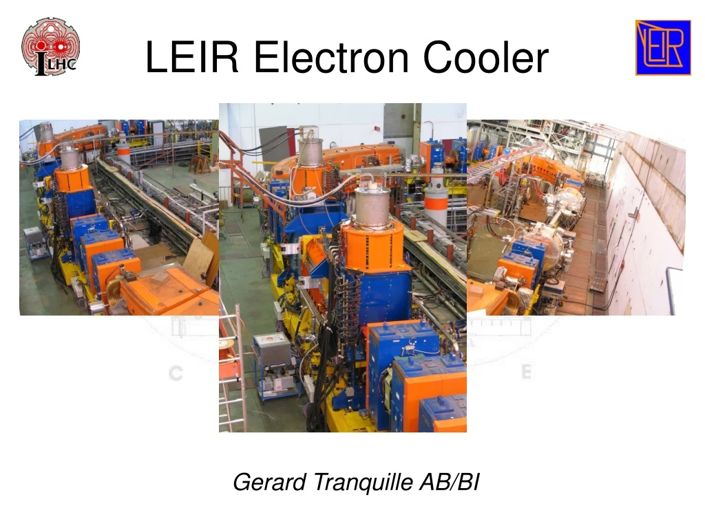
LEIR Electron Cooler Gerard Tranquille AB/BI
The Ions for LHC project • LHC needs L = 1027 cm-2s-1 at 2.7 TeV/n • 592 bunches, 7.107 ions/bunch, ε=1.5 μm, β*=0.5m • Implies 9 108 ions with ε=0.7 μm every 3.6s in LEIR • Cool and stack the freshly injected beam by electron cooling in 400 ms max • 4 injection-cooling-stacking cycles should be enough (time<1.6s) • First run, early scheme, L=5 1025 cm-2s-1 (60 bunches, 7 107 ions/bunch, b*=1) => 2.25 108 ions in LEIR.
Conclusions of 1997 tests • Stacking principle demonstrated and is compatible with the filling scheme. • Equilibrium emittance fits the LHC requirement and emittance growth is not an issue. • Factor of 2.5 missing in the total accumulated intensity in 1.6 s. • COOLING TIME LIMITED BY THE PERORMANCE OF THE GUN. • INTENSITY LIMITED BY LOSSES DUE TO CHARGE EXCHANGE AND ELECTRON-ION RECOMBINATION. 3.5x10⁸
LEIR electron cooler parameters • Electron energy range from 2 keV to 40 keV. • High perveance gun (6 mP at 2.3 keV => Ie = 600 mA). • Variable electron beam density. • Cold electron beam, Et<100 meV, E//<1 meV. • Adiabatic expansion. • Maximum cooling length possible. 2.5m. • Homogeneous magnetic guiding field (DBt/B//<10-4). • “pancakes”. • Efficient collection of the electron beam (DIe/Ie<10-4). • Electrostatic deflector plates.
The electron gun • Convex thermionic cathode at high voltage. Cathode radius = 14mm. • Control electrode shapes the electron beam density. • Equivalent perveance of 6 mP on the border and a factor of 10 less in the centre. • Grid electrode determines the intensity. • The gun is immersed in a strong longitudinal field (2.35 kG).
Variable density profiles Electron beam profiles with control electrode potentials Uc = 0V, +100V, +200V, +350V, +400V, +600V, grid potential Ug=500V and cathode potential Ucath = 1000V. Vc = -100 V
Adiabatic expansion • Needed for: • Adapting the electron beam size to the injected beam size for optimum cooling. Bo=0.235T, B=0.075T, ro=14mm => r=24.8mm • Reducing the magnetic field in the toroids, thus reducing the closed orbit distortion. • Reducing the transverse thermal temperature of the electron beam. Bo=0.235T, B=0.075T, Eo=100meV => E=32meV
The electrostatic bend • Electrons experience a centrifugal force in the toroid. • This drift can be compensated by an additional magnetic field in the opposite direction. • Reflected and secondary electrons however are excited by this field and can oscillate between the gun and collector before being lost. • Complete compensation is obtained by superimposing an electric field on the magnetic field
Magnetic Field Measurements Longitudinal field Vertical field Adjustment of the vertical field component In the cooling section (Bt/B < 10-4). Horizontal field
Electron Beam Measurements Electron beam position is measured by modulating the intensity via the grid electrode. Electron current vs. grid and control electrode voltage for an electron beam energy of 2.3 keV. PU signal with electron beam modulation Electron trajectory is adjusted using 22 steering coils.
Beam Cooling Studies Momentum spread evolution measured on the Schottky PU with (bottom) and without (top) electron cooling. Horizontal beam size evolution measured with an ionisation profile monitor with (bottom) and without (top) electron cooling. • Transverse cooling difficult to confirm due to lack of reliable instrumentation. • Schottky spectra show that the beam becomes unstable. • Lifetime in the presence of electron cooling decreases (effect of IPMV wire?).
Summary of what has been achieved • Electron cooler construction & pre-commissioning successfully carried out by BINP (Oct 2003 – Dec 2004) • Initial magnet measurements and adjustments. • Cathode conditioning and electron beam generation. • Integration into LEIR • Magnetic system readjusted after delivery at CERN. • Electrical and water connections, commissioning of power supplies, Faraday cage installation, interlock system. • UHV preparations, first bakeout in June, second bakeout needed in September due to leak in sector. • Cooler commissioning started in October • Stable 400 mA electron beam obtained at 2.3 keV. • Electron beam collection efficiency of 99.96%. • Static vacuum of 6x10-12 torr (limited by leak on a gun ceramic). • No clear signal of beam cooling (for the time being).
What Still Needs to be Done • Clearly demonstrate beam cooling • Check electron-ion alignment. • H & V ionisation profile monitors. • Schottky diagnostics. • (A down-charge detector in the downstream bending magnet would be useful) • Continue electron beam studies • Increase current to 600 mA at 2.3 keV & improve collection efficiency. • Steering with 22 correction coils, use electrostatic bends. • Study the influence of the beam distribution on the Pb beam lifetime. • Replace electron gun • BINP will deliver shortly, co-ordination with AT/VAC for intervention.