Download
1 / 35
350 likes | 517 Views
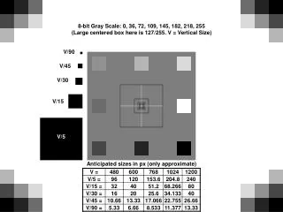
sizes for PID & shields. M. Apollonio – University of Oxford. Consider different optics for MICE Consider the maximum radius a particle can reach in the tracker (TK) = 15 cm the absorber (ABS) = 15 cm the RF windows (RF) = 21.3 cm It can be shown that b ~ <R 2 >

E N D
sizes for PID & shields M. Apollonio – University of Oxford CM17 -CERN- (22/2-25/2/2007)
Consider different optics for MICE • Consider the maximum radius a particle can reach in the tracker (TK) = 15 cm the absorber (ABS) = 15 cm the RF windows (RF) = 21.3 cm It can be shown that b ~ <R2> • Propagate the radius throughout MICE according to • These curves represent the ENVELOPE of the beam which just touches the TK, the ABS, the RF and the diffuser == muons with a given amplitude == MIN size of diffuser MIN radii in the downstream region CM17 -CERN- (22/2-25/2/2007)
CAVEAT: Z_diff=-6.010 m (corrected w.r.t. the original presentation given at a previous an.meeting) CM17 -CERN- (22/2-25/2/2007)
current diffuser position ideal minimum RD RD-TRK= 15.1 cm RD-ABS= 13.5 cm RD-RF= 11.9 cm CM17 -CERN- (22/2-25/2/2007)
Wang-200-42 Z-downstream: shield-in shield-out SW TOF KL CM17 -CERN- (22/2-25/2/2007)
inside TKs • inside ABS • inside RF current diffuser position ideal minumum RD RD-TRK= 15.2 cm RD-ABS= 13.8 cm RD-RF= 11.9 cm Every m in the TKs will traverse both ABS and RF RD must be as large as possible 10 cm is definitely too small !!! CM17 -CERN- (22/2-25/2/2007)
Wang 207-200-193 (with energy loss) R grows linearly far from the solenoid (beta ~ z2) CM17 -CERN- (22/2-25/2/2007)
Wang-240-42 RD-TRK= 15.1 cm RD-ABS= 14.8 cm RD-RF= 13.0 cm CM17 -CERN- (22/2-25/2/2007)
Wang-240-42 CM17 -CERN- (22/2-25/2/2007)
NF-200-42 RD-TRK= 15.2 cm RD-ABS= 13.5 cm RD-RF= 10.5 cm CM17 -CERN- (22/2-25/2/2007)
NF-200-42 CM17 -CERN- (22/2-25/2/2007)
SFOFO-170-15 RD-TRK= 15.3 cm RD-ABS= 22.1 cm RD-RF= 10.8 cm CM17 -CERN- (22/2-25/2/2007)
SFOFO-170-15 CM17 -CERN- (22/2-25/2/2007)
RD-TRK= 14.6 RD-ABS= 30.9 RD-RF= 11.5 SFOFO-140-7 CM17 -CERN- (22/2-25/2/2007)
SFOFO-140-7 CM17 -CERN- (22/2-25/2/2007)
Summary of min R – DIFFUSER (cm) CM17 -CERN- (22/2-25/2/2007)
Definition of MIN Radius for PIDs and SHIELD holes !!! NOT IN SCALE (but figures should be correct) 250 100 100 50 250 solenoid end plate 40 750 650 40 700 KL SW m max radius 50 TOF 6399.5 6499.5 6574.5 6649.5 6729.5 7429.5 6524.5 6599.5 6689.5 CM17 -CERN- (22/2-25/2/2007)
According to the defs given in previous slides these are the min radii (a) for the shield (to let every m pass) and (b) for the PIDs (to accept every m) Slightly out ? tolerances Within tolerances 600x600 700x700 mm2 iron shield 1000x1000 mm2 Is it a problem? CM17 -CERN- (22/2-25/2/2007)
Wang-200-42 like having a 20 cm shorter SW calorimeter But only for the outer muons Z-downstream: shield-in shield-out SW TOF KL CM17 -CERN- (22/2-25/2/2007)
conclusions the maximum radii for particles traversing MICE are propagated (from the max R in 3 different places) through the apparatus (TKs, ABS, RF) Considering several optics: min Radius (at fixed position z=-6010 mm) for the diffuser is defined: in order to have particles in the TKs it turns out Rd should be as large as possible (compatible with mechanical contraints) In any case RD=10 cm seems to be small ! min radii for downstream shield holes are computed upon the requirement of accepting every m from trackers min radii for PIDs are computed upon the requirement of having the maximal acceptance within the detector: this condition can be probably relaxed Real B field in the “shield area” should take into account real map. This is just an approximation whose purpose is giving some initial figures CM17 -CERN- (22/2-25/2/2007)
radial size for the diffuser M. Apollonio – University of Oxford CM17 -CERN- (22/2-25/2/2007)
Z=-6010 mm for the upstream face of the diffuser. This is • a figure established long time ago (CR, CM14 Osaka - 2006) • I focussed on the radial size of it • propagate muons back from centre tracker to the diffuser • record x,y position and check whether they fall within the • diffuser • generate beams upstream with proper ALPHA/BETA and • go through the diffuser • compute emittances check bias due to r_cut • would like to convince you that R=10 cm is a bit tight and • propose some solution CM17 -CERN- (22/2-25/2/2007)
ICOOL sim, Pz=200 MeV/c diffuser Z=-6.010 -5.2 m CM17 -CERN- (22/2-25/2/2007)
r=10 cm r=15 cm CM17 -CERN- (22/2-25/2/2007)
Beam fraction within radius R0 CM17 -CERN- (22/2-25/2/2007)
try to see it another way … generate (gaussian) beams BEFORE DIFFuser: 1- thickness of 7 mm inflation: 2.7 6.5 mm rad (BETA=76 cm / ALPHA=.20 ) 2- thickness of 12.7 mm inflation: 2.7 10 mm rad (BETA=127cm / ALPHA=.37 ) 3- thickness of 8 mm inflation: 1.9 10 mm rad (BETA=189 cm / ALPHA=1.14 ) 4- thickness of 14.2 mm inflation: 3.4 10 mm rad (BETA=128 / ALPHA=.4) calculate emi before/after diffuser for several radii (compare with a large radius case) Pz=209 MeV/c +/- 10% Pz=148 MeV/c +/- 10% Pz=267 MeV/c +/- 10% CM17 -CERN- (22/2-25/2/2007)
ICOOL sim diffuser Z=-6.010 CM17 -CERN- (22/2-25/2/2007)
A tentative scheme for the diffuser trying to exploit all the radial space (15 cm) within the tin can envelope being compatible with mechanical contraints CM17 -CERN- (22/2-25/2/2007)
Muons selected on the overall channel ideal disc 7mm 15.5cm 7mm Emi inflation in single layer lead diffuser: 2.8 6.1 mm rad emi(after diff)=6 mm rad CM17 -CERN- (22/2-25/2/2007)
realistic diffuser 7mm 7mm 5cm 15.5cm 7mm 7mm Emi inflation in a staggered lead diffuser: 2.8 6.1 mm rad fixed annulus movable disc + support CM17 -CERN- (22/2-25/2/2007)
7mm 7mm 5cm 15.5cm 7mm Emi inflation with a single layer of lead (small radius): 2.8 5.3 mm rad CM17 -CERN- (22/2-25/2/2007)
Proposal to accommodate many configurations 6, 10 mm rad @ Pz=200 MeV/c 10 mm rad @ Pz=140 MeV/c 10 mm rad @ Pz=240 MeV/c …just a sketch (see Stephanie/Wing drawings) diffuser tracker 7 to 14.2mm 30 cm 24 to 27 cm envelope 8 mm Supports (outer can/disc support): Al Pb diffuser disc and outer annulus CM17 -CERN- (22/2-25/2/2007) 12.7 mm
emi(R)/emi(R=30 cm) single disc staggered discs Pz=148 MeV/c, emi=10mm rad, B=2.9 T Pz=209 MeV/c, emi=10mm rad, B=4 T Pz=267 MeV/c, emi=10mm rad, B=4 T Emittance bias as a function of R_diff (partial inflation) R_diff CM17 -CERN- (22/2-25/2/2007)
SUMMARY • a diffuser with R=10 cm is too small. We • should try to use all the space available • the choice of R_diff can be inspired by • the emi_bias plot, in which case you can • choose between 12 and 13.5 cm • the “staggered” solution provide uniform • inflation (till R~15 cm) and is equivalent • to the ideal full disc case. Important for • high emittances and low momenta CM17 -CERN- (22/2-25/2/2007)