Download
1 / 14
140 likes | 250 Views
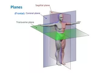
This overview focuses on the three essential planes that govern network operations: the User Plane, Control Plane, and Management Plane. The Management Plane is responsible for configuring data tables, handling routing protocols, performance management, fault management, and security. The Control Plane involves protocols for connection setups and call control, either at network layer switches or transport layer endpoints. Lastly, the User Plane handles the actual data flow, utilizing routing protocols to ensure efficient data dissemination. This examination highlights their functions, protocols, and interactions in network infrastructure.

E N D
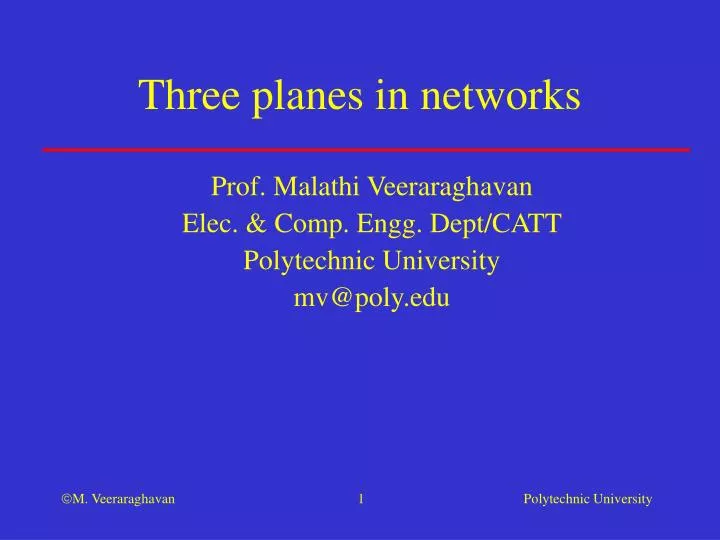
Three planes in networks Prof. Malathi Veeraraghavan Elec. & Comp. Engg. Dept/CATT Polytechnic University mv@poly.edu
User plane, control plane, and management plane • Management plane: consists of all the protocols needed to “configure” data tables for the operation of the network • For example, protocols for routing data dissemination (distributed or centralized) • Other functions: performance, fault mgmt., accounting, security • Control plane: • Connection control protocols • in CO networks, this includes connection setup at each switch (connections at the network layer) • in CL networks, this includes connection setup only at the endpoints (connections at the transport layer, if the TL protocol is reliable) • Call control protocols • User plane: protocols for the actual flow of data
Routing protocol Routing protocol Routing protocol Dest. Dest. Dest. Next hop Next hop Next hop III-* III-* B III IV B Routing tables Routing protocol in all three types of networks - Phase 1 II III Host B I Host A V IV • Routing protocols exchange topology/loading/reachability information • Routes to destinations are precomputed and stored in routing tables
Connection setup (B) b a a Connection setup Connection setup b c b d c c a Connection setup d IN Port /Label IN Port /Label IN Port /Label OUT Port/Label OUT Port/Label OUT Port/Label d/L1 a/L1 a/L2 b/L3 c/L2 c/L1 Virtual circuit Signaling protocol for NL connection setup in a PS CO network - Phase 2 • Connection setup consists of each switch on the path • Route lookup for next hop node to reach destination • CAC (Connection Admission Control) for buffer and BW • Writing the input/output label mapping tables and programming the scheduler II III I Host A Host B V IV
Connection setup (B) b a a Connection setup Connection setup b c b d c c a Connection setup d IN Port /Timeslot OUT Port/Timeslot IN Port /Timeslot IN Port /Timeslot OUT Port/Timeslot OUT Port/Timeslot a/1 c/2 d/2 a/2 b/1 c/2 Circuit Signaling protocol for NL connection setup in a CS CO network - Phase 2 • Connection setup consists of each switch on the path • Route lookup for next hop node to reach destination • CAC (Connection Admission Control) for BW (note: no buffers) • Writing the port/timeslot/l mapping table II III I Host A Host B V IV
IN Port /Label OUT Port/Label L3 L1 L1 L2 a/L1 c/L2 User-plane packet forwarding in a PS CO network - Phase 3 • Labels are VPI/VCIs in ATM • Labels are translated from link-to-link II b a a III I Host A b c Host B b d c c V IV a d
1 2 IN Port /Timeslot OUT Port/Timeslot a/1 c/2 1 1 2 2 1 2 User-plane actions in a circuit-switched network - Phase 3 II • Bits arriving at switch I on time slot 1 on port a are switched to time slot 2 of port c b a a III I Host A b c Host B b d c c V IV a d
B B B B User-plane packet forwarding in a CL PS network - Phase 3 II • Packet headers carry destination host address (unchanged as it passes hop by hop) • Each CL packet switch does a route lookup to determine the outgoing port/next hop node b a a III I Host A b c Host B b d c c V IV a d
Addressing • Where are endpoint addresses used: • In CL PS networks, endpoint addresses are carried in packet headers • In CO networks, be it PS or CS, endpoint addresses are carried in connection setup messages
Summarized addresses • What are summarized addresses? • Why summarize addresses?
Summarized addresses • What are summarized addresses? • An address that represents a group of endpoint addresses • e.g., all 212 numbers, 128.238 IP addresses • Why summarize addresses? • Reduces routing table sizes – hold one entry for a summarized address instead of a large number of individual addresses • Reduces routing message lengths that convey reachability information
Examples of signaling protocols • SS7 (Signaling System No. 7) network (with its SS7 protocol stack) carries signaling messages to set up and release circuits in a telephone network
Examples of routing protocols • In the Internet: • Link-state routing protocols, such as Open Path Shortest First (OSPF) • Distance-vector based routing protocols, such as Routing Information Protocol (RIP) • In telephone networks: • Real-Time Network Routing (RTNR)
Examples of addressing schemes • Internet • 4-byte IP addresses • Telephone networks • 8-byte E.164 address (telephone number) • ATM networks • 20-byte ATM End System Address (AESA)