Sectional Views
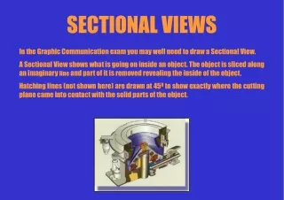
Sectional Views. Engineering Graphics & Design. By John Kirby. Sectional Views. Cut into the drawing Reduce confusion of excessive hidden lines Hatch lines represent the interior mass Aid visualizing the internal workings of a drawing. Alphabet of Lines. Crosshatching.

Sectional Views
E N D
Presentation Transcript
Sectional Views Engineering Graphics & Design By John Kirby
Sectional Views • Cut into the drawing • Reduce confusion of excessive hidden lines • Hatch lines represent the interior mass • Aid visualizing the internal workings of a drawing
Crosshatching Crosshatching patterns represent the various metals and materials used in Engineering Graphics & Design.
Full Sections • Cuts the drawing completely apart • Cuts generally horizontal or vertical from one end to the other • Cuts often pass through the center of the drawing Acceptable styles for cutting plane lines
Full Section Part Outline – heavy weight line Cutting Plane Line Crosshatching
Half Sections • A half section is one half of a full section • ¼ of the object is cut • Two cutting plane lines at right angles • ½ of the view is represented by the cut • Used when drawing symmetrical objects
Half Sections of 4 Step Pulley Part Outline – heavy weight line Half Section– cutting plane line drawn at right angle
Offset Sections • Cutting plane lines are shifted to include missing details • Cutting plane lines only view areas along the cutting plane line • Cutting plane lines are offset to include more details
Offset Section Cutting Plane line does not include holes behind the line. Offset Cutting Plane line does includes holes along the line.
Break Out Sections • Removes a defined area of material • Exposes obscured parts or features in an existing drawing view • View must be associated to a sketch that contains the profile defining the break out boundary
Break Out View of Part Break Out View exposes inside of part with counter bore with threaded hole
Break Out View of Assembly Drawing A Break Out View can also be utilized on assembly drawings to view inside of assemblies.
Detail View • Represents a specified portion of a view • Assigning any scale to the view • Used a zoom to enlarge areas better represented by enlarging for clarity
Detail View of Box Assembly Box Assembly is drawn ½ scale where the detail view is drawn full scale. Dimensions included on Detail B.
Broken View • Used when the component view exceeds the length of the drawing • Used when scaling the component view to fit the drawing makes the component view prohibitively small • Used view contains large areas of nondescript geometry
Broken View of an Assembly Drawing Break Lines inserted to reduce the actual length of the assembly. Dimension line above also denotes the break. Can you identify and label the other three types of lines used in the drawing?
Auxiliary View • Helper view that aligns with the view from which it is projected • Are used when true orthographic projections would distort the true shape of the object • Are aligned with the projection lines of the auxiliary view
Three View Projection without Auxiliary View Representation The top and right side views do not truly represent the actual shape of the part.
Auxiliary View with Detail Section Projected View aligns with Detail B to insure a true shape of the part.
Exceptions for Clarity Offset Section Full Section Which view best represents the pulley?
Can you identify the two types of sections used below? A half section A break out section
What type of section is represented below? When is this type of view used?
What type of view is represented below? When is this technique applied?
There are two drawing techniques mentioned earlier in the drawing below: Identify each and explain.
Identify the type of cutting plane below: Why was it used in this drawing?