Download

1 / 11
150 likes | 452 Views
Molecular Orbital Energy Diagrams (16.7). MO energy diagrams are useful in that they show how atomic orbitals from different atoms may combine to molecular orbitals Sigma bonds form from s- and p-orbitals, pi bonds from p-orbitals

E N D
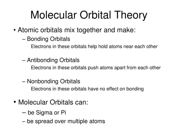
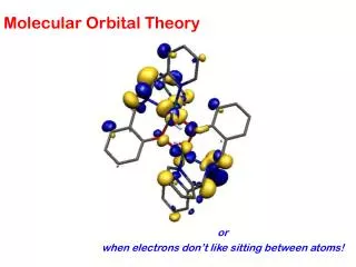
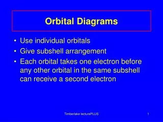
Molecular Orbital Energy Diagrams (16.7) • MO energy diagrams are useful in that they show how atomic orbitals from different atoms may combine to molecular orbitals • Sigma bonds form from s- and p-orbitals, pi bonds from p-orbitals • Orbital energies and shapes dictate which AOs are used to generate MOs • Valence atomic orbitals are used to form chemical bonds • Two AOs combine to form a bonding orbital and and anti-bonding orbital • Bonding orbitals have considerable electron density between atoms, anti-bonding orbitals have a node in between the two atoms • AOs of similar energy combine more readily to form MOs • Electrons from each atom are used to fill the MO energy diagram • Lowest energy orbitals are filled first • Up to two electrons can be placed in a single MO • For degenerate MOs, one electron is placed in each MO before the electron is paired up
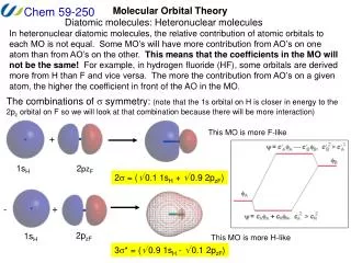
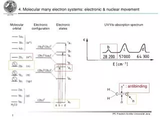
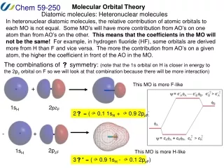
MO Diagrams of Diatomic Molecules (16.7 and 16.11) • For homonuclear diatomic molecules, the orbitals on each atom are paired with their counterparts on the other atom since they are degenerate • s-orbitals combine to form σ- and σ*-orbitals, as do p-orbitals along bond axis (usually designated as pz-orbitals) • px- and py-orbitals combine to form a pair of degenerate π- and π*-bonds • Oxygen is an interesting case, and only MO theory describes its behavior correctly • MO diagram differs from Lewis structure (how?) • Heteronuclear diatomic molecules have similar MO diagrams, but AOs are no longer degenerate • More electronegative the atom, the lower in energy the atomic orbitals • AOs of similar energy overlap more readily
Bond Orders, Energies, and Lengths (16.10) • Bond orders of diatomic molecules can be determined by summing up bonds and anti-bonds • Each bond (σ or π) adds to the bond order • Each anti-bond reduces the bond order • Partially filled bonds and anti-bonds also contribute to bond order (e.g., oxygen) • Bond order and bond energy can be determined from bond order information • More bonds means stronger bonds • More bonds means shorter bonds • One can also predict the stability of ions based on MO diagrams • Adding electrons to bonding orbitals strengthen bonds, removing electrons from bonding orbitals weakens them • Adding electrons to anti-bonding orbitals weakens bonds, removing electrons from anti-bonding orbitals strengthens bonds