Ultrasonic Technology
Ultrasonic Technology. Presented by Henry E. Cook Three Rivers Technical Conference 2010 August 3rd & 4th, 2010 - Elk River, MN. Basic Principles of Ultrasonic Testing.

Ultrasonic Technology
E N D
Presentation Transcript
Ultrasonic Technology Presented by Henry E. Cook Three Rivers Technical Conference 2010 August 3rd & 4th, 2010 - Elk River, MN
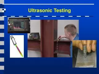
Basic Principles of Ultrasonic Testing Ultrasonic Testing (UT) uses high frequency sound energy to conduct examinations and make measurements. Ultrasonic inspection can be used for flaw detection/evaluation, dimensional measurements, material characterization, and more.
Data Presentation • Ultrasonic data can be collected and displayed in a number of different formats. The three most common formats are know in the NDT world as A-scan, B-scan and C-scan • Each presentation mode provides a different way of looking at and evaluating the region of material being inspected. • Modern computerized ultrasonic scanning systems can display data in all three presentation forms simultaneously.
Present State of Ultrasonics • Many ultrasonic flaw detectors have a trigonometric function that allows for fast and accurate location determination of flaws when performing shear wave inspections. • Cathode ray tubes, for the most part, have been replaced with LED or LCD screens. These screens, in most cases, are extremely easy to view in a wide range of ambient lighting. • Transducers can be programmed with predetermined instrument settings. The operator only has to connect the transducer and the instrument will set variables such as frequency and probe drive.
Present State of Ultrasonics • Along with computers, motion control and robotics have contributed to the advancement of ultrasonic inspections. • Computers can be programmed to inspect large, complex shaped components, with one or multiple transducers collecting information. Automated systems typically consisted of an scanning system, and recording system for a printout of the scan. • The resultant C-scan provides a plan or top view of the component. Scanning of components is considerably faster than contact hand scanning, the coupling is much more consistent. • The scan information is collected by a computer for evaluation, transmission to a customer, and archiving.
Specifications • Three 32 bit microprocessors • Manual PRF Control: Allows the operator to manually adjust the pulse repetition frequency (PRF) from 1 Hz to 5KHz in 5 Hz increments. • Extended Range: 0.112" to 800“ • Time Of Flight (TOF) or Amplitude Measurements • DAC & DAG
Specifications • BB, 0.5, 1.0, 2.25. 5.0, 10MHz tuning incorporating HiQ, LowQ Digital Band Pass Filtering • DAC & DAG • Selectable Tunable Square Wave Pulser/ Spike Pulser: Allows the operator to tune the pulse width of the square wave pulser to optimize transducer performance. • BB, 0.5, 1.0, 2.25. 5.0, 10MHz tuning incorporating HiQ, LowQ Digital Band Pass Filtering
Specifications • A, B and C-Scan imaging native • Supports manual scanners, inexpensive, light weight Li-ion battery powered semi-automated scanners as well as the capability to support fully automated stepper or servo operated high speed, high resolution scanners via Systems external "Drive Box" interface. • SD Card: Up to 32GB user removable Flash Card • I/O: USB 2.0 Connectivity • Battery Operation
Specifications Battery Powered, Cantilever Arm Scanner is an innovation permitting the operator to work on a line entirely AC Power free for up to 6 hours per charge. This scanner is a controlled motion scanner connecting directly to the RAPTOR itself and a speed controlled battery pack.
Specifications StringScan - Precision Flexible Arm Manual Mini-Scanner affords a pre-tensioned fluid motion incorporating a zero backlash string motors and when used a Imaging Flaw Detector converts triangulated motion to X-Y coordinent motion. Accuracy and repeatability to 0.040“.
Specifications Other scanner configurations supported
Imaging Capabilities. Live RF Demonstrating IP Block Gate and Threshold Triggering during capture of C-Scan
Imaging Capabilities. Spreadsheet View of Corrosion Sample. In this view, the software displays the maximum number of data cells it can with actual data values
Imaging Capabilities. Standard "Zoom" view of the mini 'C' Scan in the upper right corner will show the outline of the zoomed view
Imaging Capabilities. This is a 3 view 'C' & Dual axis 'B' scan example of a pipe with actual corrosion. Thickness displayed at cross hair intersection
Imaging Capabilities. 3D high resolution "wire frame" view of corrosion sample
Imaging Capabilities. Color Palette histogram of erosion sample. Higher values of a given color represent more data around that particular thickness or amplitude data
Conclusion. • A new category of Ultrasonic Flaw Detectors offering full imaging capability in a standard hand held flaw detector. • High performance flaw detector offering features and functionality including C-Scan, Dual Axis B-Scan, 3D, Pan & Zoom, Spreadsheet review.