Download

1 / 33
330 likes | 526 Views
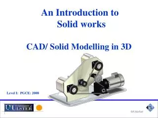
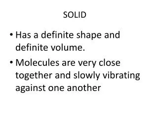
SOLID MODELLING. Why solid modeling?. Recall weakness of wireframe and surface modeling Ambiguous geometric description incomplete geometric description lack topological information Tedious modeling process Awkward user interface. Solid model.

E N D
SOLID MODELLING disediakan oleh Suriati bte Sadimon GMM, FSKSM, UTM, 2004
Why solid modeling? • Recall weakness of wireframe and surface modeling • Ambiguous geometric description • incomplete geometric description • lack topological information • Tedious modeling process • Awkward user interface disediakan oleh Suriati bte Sadimon GMM, FSKSM, UTM, 2004
Solid model • Solid modeling is based on complete, valid and unambiguous geometric representation of physical object. • Complete points in space can be classified.(inside/ outside) • Valid vertices, edges, faces are connected properly. • Unambiguous there can only be one interpretation of object disediakan oleh Suriati bte Sadimon GMM, FSKSM, UTM, 2004
Solid model • Analysis automation and integration is possible only with solid models has properties such as weight, moment of inertia, mass. • Solid model consist of geometric and topological data • Geometry shape, size, location of geometric elements • Topology connectivity and associativity of geometric elements non graphical, relational information disediakan oleh Suriati bte Sadimon GMM, FSKSM, UTM, 2004
Solid model representation schemes • Constructive solid geometry (CSG) • Boundary representation (B-rep) • Spatial enumeration • Instantiation. disediakan oleh Suriati bte Sadimon GMM, FSKSM, UTM, 2004
Constructive solid geometry (CSG) • Objects are represented as a combination of simpler solid objects (primitives). • The primitives are such as cube, cylinder, cone, torus, sphere etc. • Copies or “instances” of these primitive shapes are created and positioned. • A complete solid model is constructed by combining these “instances” using set specific, logic operations (Boolean) disediakan oleh Suriati bte Sadimon GMM, FSKSM, UTM, 2004
Constructive solid geometry (CSG) • Boolean operation • each primitive solid is assumed to be a set of points, a boolean operation is performed on point sets and the result is a solid model. • Boolean operation union, intersection and difference • The relative location and orientation of the two primitives have to be defined before the boolean operation can be performed. • Boolean operation can be applied to two solids other than the primitives. disediakan oleh Suriati bte Sadimon GMM, FSKSM, UTM, 2004
Constructive solid geometry (CSG)- boolean operation • Union • The sum of all points in each of two defined sets. (logical “OR”) • Also referred to as Add, Combine, Join, Merge A B A B disediakan oleh Suriati bte Sadimon GMM, FSKSM, UTM, 2004
Constructive solid geometry (CSG)- boolean operation • Difference • The points in a source set minus the points common to a second set. (logical “NOT”) • Set must share common volume • Also referred to as subtraction, remove, cut A B A - B disediakan oleh Suriati bte Sadimon GMM, FSKSM, UTM, 2004
Constructive solid geometry (CSG)- boolean operation • intersection • Those points common to each of two defined sets (logical “AND”) • Set must share common volume • Also referred to as common, conjoin A B A B disediakan oleh Suriati bte Sadimon GMM, FSKSM, UTM, 2004
Constructive solid geometry (CSG)- boolean operation • When using boolean operation, be careful to avoid situation that do not result in a valid solid A B A B disediakan oleh Suriati bte Sadimon GMM, FSKSM, UTM, 2004
Constructive solid geometry (CSG)- boolean operation • Boolean operation • Are intuitive to user • Are easy to use and understand • Provide for the rapid manipulation of large amounts of data. • Because of this, many non-CSG systems also use Boolean operations disediakan oleh Suriati bte Sadimon GMM, FSKSM, UTM, 2004
Constructive solid geometry (CSG)- data structure • Data structure does not define model shape explicitly but rather implies the geometric shape through a procedural description • E.g: object is not defined as a set of edges & faces but by the instruction : union primitive1 with primitive 2 • This procedural data is stored in a data structure referred to as a CSG tree • The data structure is simple and stores compact data easy to manage disediakan oleh Suriati bte Sadimon GMM, FSKSM, UTM, 2004
Constructive solid geometry (CSG)- CSG tree • CSG tree stores the history of applying boolean operations on the primitives. • Stores in a binary tree format • The outer leaf nodes of tree represent the primitives • The interior nodes represent the boolean operations performed. disediakan oleh Suriati bte Sadimon GMM, FSKSM, UTM, 2004
Constructive solid geometry (CSG)- CSG tree + - disediakan oleh Suriati bte Sadimon GMM, FSKSM, UTM, 2004
Constructive solid geometry (CSG)- not unique • More than one procedure (and hence database) can be used to arrive at the same geometry. - disediakan oleh Suriati bte Sadimon GMM, FSKSM, UTM, 2004
Constructive solid geometry (CSG) representation • CSG representation is unevaluated • Faces, edges, vertices not defined in explicit • CSG model are always valid • Since built from solid elements. • CSG models are complete and unambiguous disediakan oleh Suriati bte Sadimon GMM, FSKSM, UTM, 2004
Constructive solid geometry (CSG) - advantage • CSG is powerful with high level command. • Easy to construct a solid model – minimum step. • CSG modeling techniques lead to a concise database less storage. • Complete history of model is retained and can be altered at any point. • Can be converted to the corresponding boundary representation. disediakan oleh Suriati bte Sadimon GMM, FSKSM, UTM, 2004
Constructive solid geometry (CSG) - disadvantage • Only boolean operations are allowed in the modeling process with boolean operation alone, the range of shapes to be modeled is severely restricted not possible to construct unusual shape. • Requires a great deal of computation to derive the information on the boundary, faces and edges which is important for the interactive display/ manipulation of solid. disediakan oleh Suriati bte Sadimon GMM, FSKSM, UTM, 2004
solution • CSG representation tends to accompany the corresponding boundary representation hybrid representation • Maintaining consistency between the two representations is very important. disediakan oleh Suriati bte Sadimon GMM, FSKSM, UTM, 2004
Boundary representation (B-Rep) • Solid model is defined by their enclosing surfaces or boundaries. This technique consists of the geometric information about the faces, edges and vertices of an object with the topological data on how these are connected. disediakan oleh Suriati bte Sadimon GMM, FSKSM, UTM, 2004
Boundary representation (B-Rep) • Why B-Rep includes such topological information? • A solid is represented as a closed space in 3D space (surface connect without gaps) • The boundary of a solid separates points inside from points outside solid. disediakan oleh Suriati bte Sadimon GMM, FSKSM, UTM, 2004
B-Rep vs surface modeling • Surface model • A collection of surface entities which simply enclose a volume lacks the connective data to define a solid (i.e topology). • B- Rep model • Technique guarantees that surfaces definitively divide model space into solid and void, even after model modification commands. disediakan oleh Suriati bte Sadimon GMM, FSKSM, UTM, 2004
B-Rep data structure • B-Rep graph store face, edge and vertices as nodes, with pointers, or branches between the nodes to indicate connectivity. disediakan oleh Suriati bte Sadimon GMM, FSKSM, UTM, 2004
B-Rep data structure v5 f3 f2 E3 E4 E7 v4 E1 v3 f4 E2 solid f5 E6 f1 E8 v1 v2 E5 face1 face2 face3 face4 face5 Combinatorial structure /topology edge1 edge2 edge3 edge4 edge5 edge6 edge7 edge8 vertex1 vertex2 vertex3 vertex4 vertex5 Metric information/geometry (x, y, z) disediakan oleh Suriati bte Sadimon GMM, FSKSM, UTM, 2004
Boundary representation- validity • System must validate topology of created solid. • B-Rep has to fulfill certain conditions to disallow self-intersecting and open objects • This condition include • Each edge should adjoin exactly two faces and have a vertex at each end. • Vertices are geometrically described by point coordinates disediakan oleh Suriati bte Sadimon GMM, FSKSM, UTM, 2004
Boundary representation- validity • This condition include (cont) • At least three edges must meet at each vertex. • Faces are described by surface equations • The set of faces forms a complete skin of the solid with no missing parts. • Each face is bordered by an ordered set of edges forming a closed loop. • Faces must only intersect at common edges or vertices. • The boundaries of faces do not intersect themselves disediakan oleh Suriati bte Sadimon GMM, FSKSM, UTM, 2004
Boundary representation- validity • Validity also checked through mathematical evaluation • Evaluation is based upon Euler’s Law (valid for simple polyhedra – no hole) • V – E + F = 2 V-vertices E- edges F- face loops V = 5, E = 8, F = 5 5 – 8 + 5 = 2 v5 f3 f2 E3 E4 E7 v4 E1 v3 f4 E2 f5 E6 f1 E8 v1 v2 E5 disediakan oleh Suriati bte Sadimon GMM, FSKSM, UTM, 2004
Boundary representation- validity • Expanded Euler’s law for complex polyhedrons (with holes) • Euler-Poincare Law: • V-E+F-H=2(B-P) • H – number of holes in face, P- number of passages or through holes, B- number of separate bodies. V = 24, E=36, F=15, H=3, P=1,B=1 disediakan oleh Suriati bte Sadimon GMM, FSKSM, UTM, 2004
Boundary representation- ambiguity and uniqueness • Valid B-Reps are unambiguos • Not fully unique, but much more so than CSG • Potential difference exists in division of • Surfaces into faces. • Curves into edges disediakan oleh Suriati bte Sadimon GMM, FSKSM, UTM, 2004
Boundary representation- advantages • Capability to construct unusual shapes that would not be possible with the available CSG aircraft fuselages, swing shapes • Less computational time to reconstruct the image disediakan oleh Suriati bte Sadimon GMM, FSKSM, UTM, 2004
Boundary representation- disadvantages • Requires more storage • More prone to validity failure than CSG • Model display limited to planar faces and linear edges • - complex curve and surfaces only approximated disediakan oleh Suriati bte Sadimon GMM, FSKSM, UTM, 2004
Solid object construction method • Sweeping • Boolean • Automated filleting and chambering • Tweaking • Face of an object is moved in some way disediakan oleh Suriati bte Sadimon GMM, FSKSM, UTM, 2004